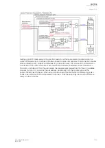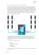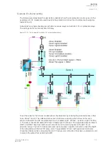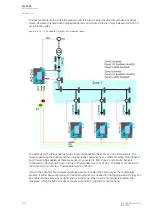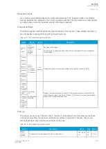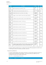
The next example is almost like the previous one: it is also a single-line diagram with AQ-2xx series
relays. However, this time each outgoing feeder has an AQ-2xx protection relay instead of an AQ-101
arc protection relay.
Figure. 5.3.12 - 79. Scheme IA1 (with AQ-200 protection relays).
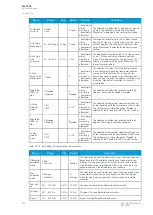
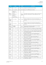
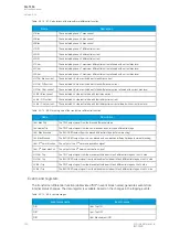
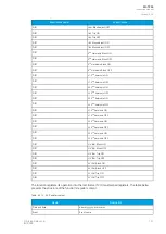
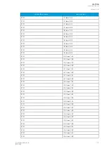
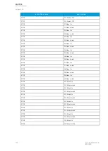
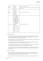
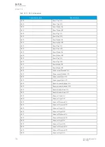
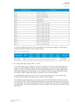
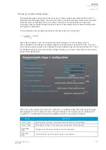
The settings for the relay supervising the incoming feeder are the same as in the first example. The
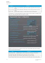
relays supervising the busbar and the outgoing feeder, however, have a different setting. Both Zones 2
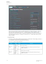
and 3 need to be enabled as there are sensors connected to both Zone 2 and 3 starts. Sensors
connected to the channel S3 are in Zone 2. Then enable Light 3 of Zone 2. The sensor connected to
the channel S2 is in Zone 3. Then enable Light 2 of Zone 3.
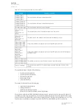
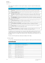
If any of the channels have a pressure sensing sensor, enable it the same way as the regular light
sensors. If either phase overcurrent or residual overcurrent is needed for the tripping decision, they can
be enabled in the same way as light sensors in the zone. When a current channel is enabled, the
measured current needs to be above the set current limit in addition to light sensing.
A
AQ
Q-T256
-T256
Instruction manual
Version: 2.06
152
© Arcteq Relays Ltd
IM00028
Summary of Contents for AQ-T256
Page 1: ...AQ T256 Transformer protection IED Instruction manual...
Page 2: ......

