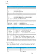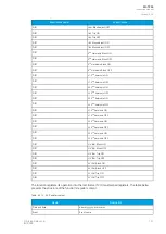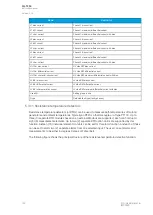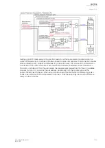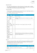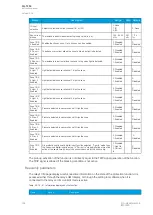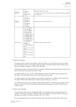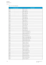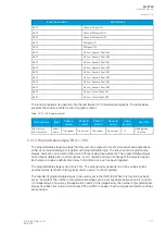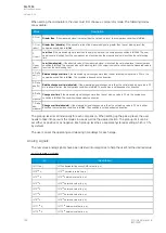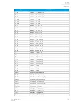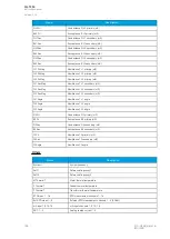
Name
Description
Range
Step Default
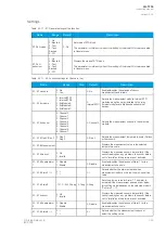
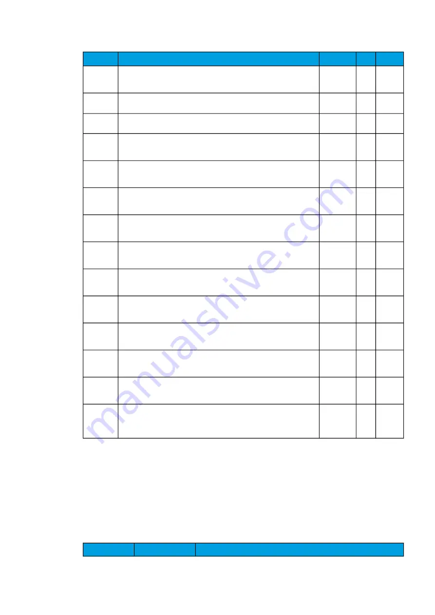
I0 input
selection
Selects the residual current channel (I01 or I02).
0: None
1: I01
2: I02
-
0: None
Res.current
pick-up
The residual current measurement's pick-up value (in p.u.).
0.05...40.00
x I
0n
0.01
x I
0n
1.2 x
I
0n
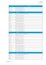
Zone1/2/3/
4 Enabled
Enables the chosen zone. Up to 4 zones can be enabled.
0: Disabled
1: Enabled
-
0:
Disabled
Zone1/2/3/
4 Ph. curr.
Enabled
The phase overcurrent allows the zone to trip when light is detected.
0: Disabled
1: Enabled
-
0:
Disabled
Zone1/2/3/
4 Res. curr.
Enabled
The residual overcurrent allows the zone to trip when light is detected.
0: Disabled
1: Enabled
-
0:
Disabled
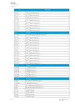
Zone1/2/3/
4 Light 1
Enabled
Light detected in sensor channel 1 trips the zone.
0: Disabled
1: Enabled
-
0:
Disabled
Zone1/2/3/
4 Light 2
Enabled
Light detected in sensor channel 2 trips the zone.
0: Disabled
1: Enabled
-
0:
Disabled
Zone1/2/3/
4 Light 3
Enabled
Light detected in sensor channel 3 trips the zone.
0: Disabled
1: Enabled
-
0:
Disabled
Zone1/2/3/
4 Light 4
Enabled
Light detected in sensor channel 4 trips the zone.
0: Disabled
1: Enabled
-
0:
Disabled
Zone1/2/3/
4 Pres. 1
Enabled
Pressure detected in sensor channel 1 trips the zone.
0: Disabled
1: Enabled
-
0:
Disabled
Zone1/2/3/
4 Pres. 2
Enabled
Pressure detected in sensor channel 2 trips the zone.
0: Disabled
1: Enabled
-
0:
Disabled
Zone1/2/3/
4 Pres. 3
Enabled
Pressure detected in sensor channel 3 trips the zone.
0: Disabled
1: Enabled
-
0:
Disabled
Zone1/2/3/
4 Pres. 4
Enabled
Pressure detected in sensor channel 4 trips the zone.
0: Disabled
1: Enabled
-
0:
Disabled
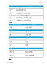
Zone1/2/3/
4 DI
Enabled
Arc protection option card digital input function selection. "Light In" mode trips
the zone when digital input is active. In "Current In" mode digital input must be
active at the same time as any of the sensor channels for the zone to trip.
0: Disabled
1: Light In
2: Current
In
-
0:
Disabled
The pick-up activation of the function is not directly equal to the TRIP signal generation of the function.
The TRIP signal is allowed if the blocking condition is not active.
Read-only parameters
The relay's
Info page displays useful, real-time information on the state of the protection function. It is
accessed either through the relay's HMI display, or through the setting tool software when it is
connected to the relay and its Live Edit mode is active.
Table. 5.3.12 - 97. Information displayed by the function.
Name
Range
Description
A
AQ
Q-T256
-T256
Instruction manual
Version: 2.06
154
© Arcteq Relays Ltd
IM00028
Summary of Contents for AQ-T256
Page 1: ...AQ T256 Transformer protection IED Instruction manual...
Page 2: ......

