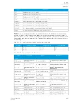
Signal
Description
I01'''f
Residual current I
01
fine* (CT card 3)
I02'''c
Residual current I
02
coarse* (CT card 3)
I02'''f
Residual current I
02
fine* (CT card 3)
ISup_3
Current measurement module voltage supply supervision (CT card 3)
UL1(2)VT2
Line-to-neutral U
L1
or line-to-line voltage U
12
(VT card 2)
UL2(3)VT2
Line-to-neutral U
L2
or line-to-line voltage U
23
(VT card 2)
UL3(1)VT2
Line-to-neutral U
L3
or line-to-line voltage U
31
(VT card 2)
U0(SS)VT2
Zero sequence voltage U
0
or synchrocheck voltage U
SS
(VT card 2)
USup_2
Voltage measurement module voltage supply supervision (VT card 2)
*NO
*NOTE
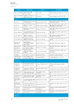
TE: There are two signals for each residual current channel in the disturbance recorder: coarse
and fine. A coarse signal is capable of sampling in the full range of the current channel but suffers a
loss of accuracy at very low currents. A fine signal is capable of sampling at very low currents and with
high accuracy but cuts off at higher currents. Table below lists performance of both channels with fine
and coarse gain.
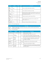
Table. 5.5.4 - 148. Residual current channel performance with coarse or residual gain.
Channel
Coarse gain range
Fine gain range
Fine gain peak
I01
0...150 A
0...10 A
15 A
I02
0...75 A
0...5 A
8 A
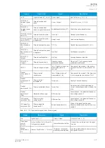
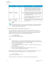
Table. 5.5.4 - 149. Digital recording channels – Measurements.
Signal
Description
Signal
Description
Currents
Pri.Pha.curr.ILx
Primary phase current ILx
(IL1, IL2, IL3)
Pha.curr.ILx TRMS Pri
Primary phase current TRMS (IL1, IL2,
IL3)
Pha.angle ILx
Phase angle ILx (IL1, IL2,
IL3)
Pos./Neg./Zero seq.curr.
Positive/Negative/Zero sequence current
Pha.curr.ILx
Phase current ILx (IL1, IL2,
IL3)
Sec.Pos./Neg./Zero seq.curr. Secondary positive/negative/zero
sequence current
Sec.Pha.curr.ILx
Secondary phase current
ILx (IL1, IL2, IL3)
Pri.Pos./Neg./Zero seq.curr.
Primary positive/negative/zero sequence
current
Pri.Res.curr.I0x
Primary residual current I0x
(I01, I02)
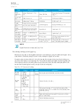
Pos./Neg./Zero
seq.curr.angle
Positive/Negative/Zero sequence current
angle
Res.curr.angle I0x
Residual current angle I0x
(I01, I02)
Res.curr.I0x TRMS
Residual current TRMS I0x (I01, I02)
Res.curr.I0x
Residual current I0x (I01,
I02)
Res.curr.I0x TRMS Sec
Secondary residual current TRMS I0x (I01,
I02)
Sec.Res.curr.I0x
Secondary residual current
I0x (I01, I02)
Res.curr.I0x TRMS Pri
Primary residual current TRMS I0x (I01,
I02)
Pri.cal.I0
Primary calculated I0
Pha.Lx ampl. THD
Phase Lx amplitude THD (L1, L2, L3)
Sec.calc.I0
Secondary calculated I0
Pha.Lx pow. THD
Phase Lx power THD (L1, L2, L3)
calc.I0
Calculated I0
Res.I0x ampl. THD
Residual I0x amplitude THD (I01, I02)
calc.I0 Pha.angle
Calculated I0 phase angle
Res.I0x pow. THD
Residual I0x power THD (I01, I02)
A
AQ
Q-T256
-T256
Instruction manual
Version: 2.06
© Arcteq Relays Ltd
IM00028
225
Summary of Contents for AQ-T256
Page 1: ...AQ T256 Transformer protection IED Instruction manual...
Page 2: ......

