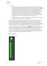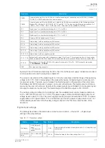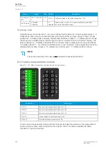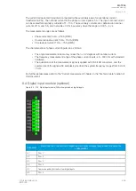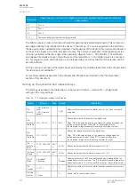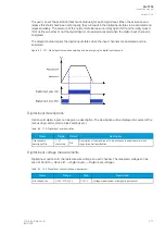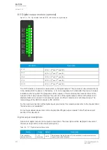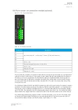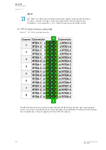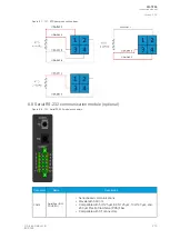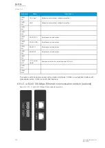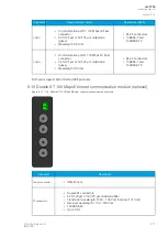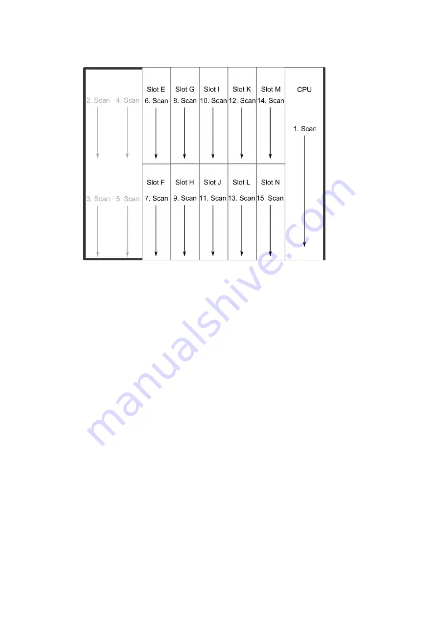
Figure. 8.1 - 123. AQ-X255 hardware scanning and I/O naming principles.
1. Scan
The start-up system; detects and self-tests the CPU module, voltages, communication and
the I/O; finds and assigns "DI1", "DI2", "DI3", "OUT1", "OUT2", "OUT3", "OUT4" and "OUT5".
2. Scan
Scans Slot A, which should always remain empty in AQ-X256 devices. If it is not empty, the
device issues an alarm.
3. Scan
Scans Slot B, which should always remain empty in AQ-X256 devices, If it is not empty, the
device issues an alarm.
4. Scan
Scans Slot C and finds the five channels of the first CT module (fixed for AQ-X256). If the
CTM is not found, the device issues an alarm.
5. Scan
Scans Slot D and finds the five channels of the second CT module (fixed for AQ-X256). If the
CTM is not found, the device issues an alarm.
6. Scan
Scans Slot E, and moves to the next slot if Slot E is empty. If the scan finds an 8DI module
(that is, a module with eight digital inputs), it reserves the designations "DI4", "DI5", "DI6",
"DI7", "DI8", "DI9", "DI10" and "DI11" to this slot. If the scan finds a DO5 module (that is, a
module with five digital outputs), it reserves the designations "OUT6", "OUT7", "OUT8",
"OUT9" and "OUT10" to this slot. The I/O is then added if the type designation code (e.g. AQ-
P215-PH0AAAA-BBC) matches with the existing modules in the device. If the code and the
modules do not match, the device issues and alarm. An alarm is also issued if the device
expects to find a module here but does not find one.
A
AQ
Q-T256
-T256
Instruction manual
Version: 2.06
© Arcteq Relays Ltd
IM00028
265
Summary of Contents for AQ-T256
Page 1: ...AQ T256 Transformer protection IED Instruction manual...
Page 2: ......


