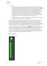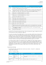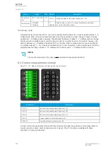
Name
Range
Step Default
Description
DIx Drop-off
time
0.000…1800.000
s
0.001
s
0.000 s
Defines the delay for the status change from 1 to 0.
DIx AC mode
0: Disabled
1: Enabled
-
0:
Disabled
Selects whether or not a 30-ms deactivation delay is added to
account for alternating current.
Scanning cycle
All digital inputs are scanned in a 5 ms cycle, meaning that the state of an input is updated every 0…5
milliseconds. When an input is used internally in the device (either in group change or logic), it takes
additional 0…5 milliseconds to operate. Theoretically, therefore, it takes 0…10 milliseconds to change
the group when a digital input is used for group control or a similar function. In practice, however, the
delay is between 2…8 milliseconds about 95 % of the time. When a digital input is connected directly
to a digital output (T1…Tx), it takes an additional 5 ms round. Therefore, when a digital input controls a
digital output internally, it takes 0…15 milliseconds in theory and 2…13 milliseconds in practice.
NO
NOTE!
TE!
The mechanical delay of the relay is no
nott included in these approximations!
8.3 Current measurement module
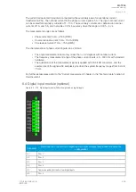
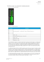
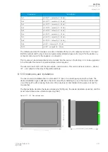
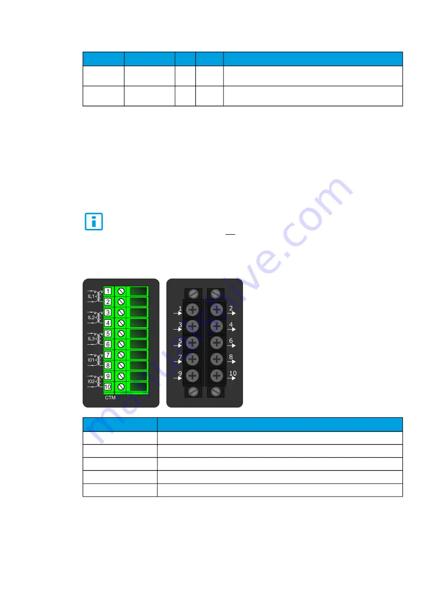
Figure. 8.3 - 125. Module connections with standard and ring lug terminals.
Connector
Description
CTM 1-2
Phase current measurement for phase L1 (A).
CTM 3-4
Phase current measurement for phase L2 (B).
CTM 5-6
Phase current measurement for phase L3 (C).
CTM 7-8
Coarse residual current measurement I01.
CTM 9-10
Fine residual current measurement I02.
A basic current measurement module with five channels includes three-phase current measurement
inputs as well as coarse and fine residual current inputs. The CT module is available with either
standard or ring lug connectors.
A
AQ
Q-T256
-T256
Instruction manual
Version: 2.06
268
© Arcteq Relays Ltd
IM00028
Summary of Contents for AQ-T256
Page 1: ...AQ T256 Transformer protection IED Instruction manual...
Page 2: ......


