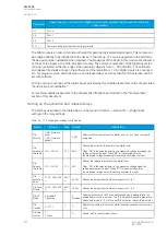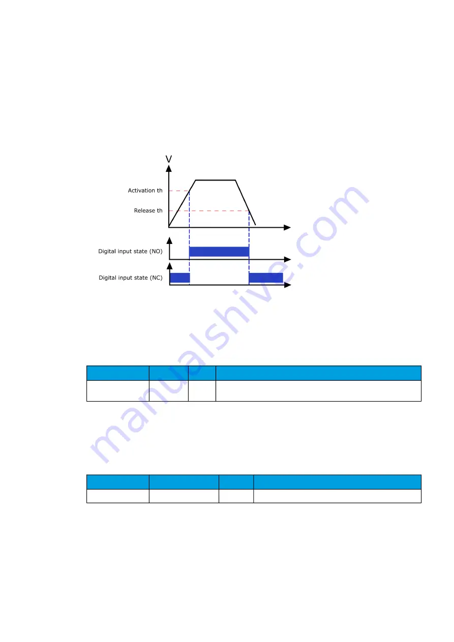
The user can set the activation threshold individually for each digital input. When the activation and
release thresholds have been set properly, they will result in the digital input states to be activated and
released reliably. The selection of the normal state between normally open (NO) and normally closed
(NC) defines whether or not the digital input is considered activated when the digital input channel is
energized.
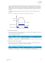
The diagram below depicts the digital input states when the input channels are energized and de-
energized.
Figure. 8.4 - 127. Digital input state when energizing and de-energizing the digital input channels.
Digital input descriptions
Option card digital inputs can be given a description. The description will be displayed in several of the
menus (logic editor, matrix, block settings etc.).
Table. 8.4 - 179. Digital input user description.
Name
Range
Default
Description
User editable
description DIx
1...31
characters
DIx
Description of the digital input. This description is used in several menu
types for easier identification.
Digital input voltage measurements
Digital input option card channels measure voltage on each channel. The measured voltage can be
seen at
Control
→
Device IO
→
Digital inputs
→
Digital input voltages.
Table. 8.4 - 180. Digital input channel voltage measurement.
Name
Range
Step
Description
DIx Voltage now
0.000...275.000 V
0.001 V
Voltage measurement of a digital input channel.
A
AQ
Q-T256
-T256
Instruction manual
Version: 2.06
© Arcteq Relays Ltd
IM00028
271
Summary of Contents for AQ-T256
Page 1: ...AQ T256 Transformer protection IED Instruction manual...
Page 2: ......


