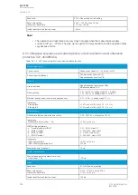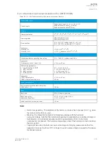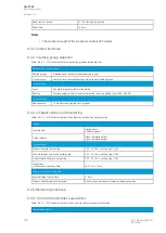
9.2.1.5 Circuit breaker failure protection (CBFP; 50BF/52BF)
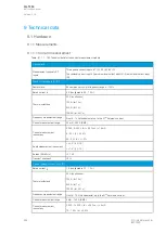
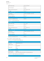
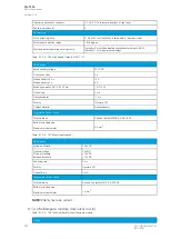
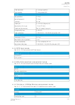
Table. 9.2.1.5 - 207. Technical data for the circuit breaker failure protection function.
Measurement inputs
Current inputs
Phase current inputs: I
L1
(A), I
L2
(B), I
L3
(C)
Residual current channel I
01
(Coarse)
Residual current channel I
02
(Fine)
Current input magnitudes
RMS phase currents
RMS residual current (I
01
, I
02
or calculated I
0
)
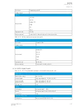
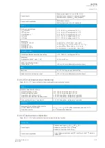
Pick-up
Monitored signals
Digital input status, digital output status, logical signals
Pick-up current setting:
- IL1…IL3
- I01, I02, I0Calc
0.10…40.00 × I
N
, setting step 0.01 × I
N
0.005…40.00 × I
N
, setting step 0.005 × I
N
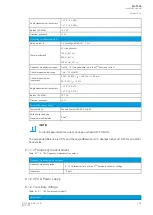
Inaccuracy:
- Starting phase current (5A)
- Starting I01 (1 A)
- Starting I02 (0.2 A)
- Starting I0Calc (5 A)
±0.5 %I
SET
or ±15 mA (0.10…4.0 × I
SET
)
±0.5 %I0
SET
or ±3 mA (0.005…10.0 × I
SET
)
±1.5 %I0
SET
or ±1.0 mA (0.005…25.0 × I
SET
)
±1.0 %I0
SET
or ±15 mA (0.005…4.0 × I
SET
)
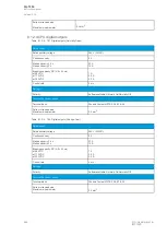
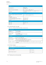
Operation time
Definite time function operating time setting
0.050…1800.000 s, setting step 0.005 s
Inaccuracy:
- Current criteria (I
M
/I
SET
ratio 1.05
→
)
- DO or DI only
±1.0 % or ±55 ms
±15 ms
Reset
Reset ratio
97 % of the pick-up current setting
Reset time
<50 ms
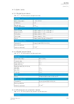
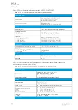
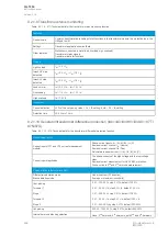
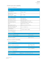
9.2.1.6 Low-impedance or high-impedance restricted earth fault/ cable end
differential protection (I0d>; 87N)
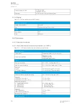
Table. 9.2.1.6 - 208. Technical data for the restricted earth fault/cable end differential function.
Measurement inputs
Current inputs
Phase current inputs: I
L1
(A), I
L2
(B), I
L3
(C)
Residual current channel I
01
(Coarse)
Residual current channel I
02
(Fine)
Current input calculations
Calculated bias and residual differential currents
Pick-up
Operating modes
Restricted earth fault
Cable end differential
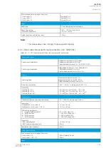
Characteristics
Biased differential with 3 settable sections and 2 slopes
Pick-up current sensitivity setting
Slope 1
Slope 2
Bias (Turnpoint 1 & 2)
0.01…50.00 % (I
N
), setting step 0.01 %
0.00…150.00 %, setting step 0.01 %
0.00…250.00 %, setting step 0.01 %
0.01…50.00 × I
N
, setting step 0.01 × I
N
Inaccuracy
- Starting
±3% of the set pick-up value > 0.5 × I
N
setting.
±5 mA < 0.5 × I
N
setting
Operation time
A
AQ
Q-T256
-T256
Instruction manual
Version: 2.06
296
© Arcteq Relays Ltd
IM00028
Summary of Contents for AQ-T256
Page 1: ...AQ T256 Transformer protection IED Instruction manual...
Page 2: ......

