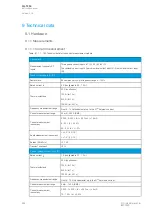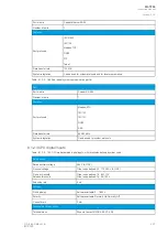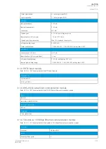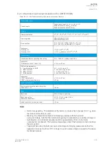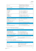
Instant operation time
1.05 x I
SET
<30 ms
Reset
Reset ratio
No hysteresis
Reset time
<40 ms
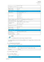
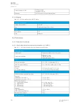
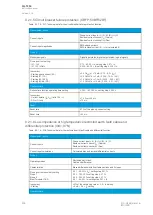
9.2.1.7 Transformer thermal overload protection (TT>; 49T)
Table. 9.2.1.7 - 209. Technical data for the transformer thermal overload protection function.
Measurement inputs
Current inputs
Phase current inputs: I
L1
(A), I
L2
(B), I
L3
(C)
Current input magnitudes
TRMS phase currents (up to the 31
st
harmonic)
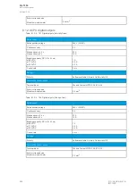
Setting specifications
Time constants τ
1 heating, 1 cooling
Time constant value
0.0…500.00 min, step 0.1 min
Service factor (maximum overloading)
0.01…5.00 × I
N
, step 0.01 × I
N
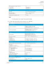
Thermal model biasing
- Ambient temperature (Set –60.0…500.0 deg, step 0.1 deg, and RTD)
- Negative sequence current
Thermal replica temperature estimates
Selectable between ºC and ºF
Outputs
- Alarm 1
- Alarm 2
- Thermal trip
- Trip delay
- Restart inhibit
0…150 %, step 1 %
0…150 %, step 1 %
0…150 %, step 1 %
0.000…3600.000 s, step 0.005 s
0…150 %, step 1 %
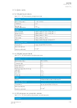
Inaccuracy
- Starting
- Operating time
±0.5 % of the set pick-up value
±5 % or ± 500 ms
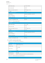
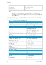
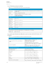
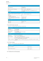
9.2.1.8 Resistance temperature detectors
Table. 9.2.1.8 - 210. Technical data of the resistance temperature detectors.
Inputs
Resistance input magnitudes
Measured temperatures measured by RTD sensors
Alarm channels
12 individual alarm channels
Settable alarms
24 alarms available (two per each alarm channel)
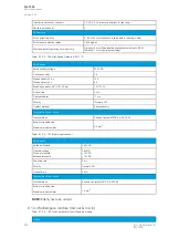
Pick-up
Alarm setting range
Inaccuracy
Reset ratio
101.00…2000.00 deg, setting step 0.1 deg (either < or > setting)
±3 % of the set pick-up value
97 % of the pick-up setting
Operation
Operating time
Typically <500 ms
A
AQ
Q-T256
-T256
Instruction manual
Version: 2.06
© Arcteq Relays Ltd
IM00028
297
Summary of Contents for AQ-T256
Page 1: ...AQ T256 Transformer protection IED Instruction manual...
Page 2: ......

