The
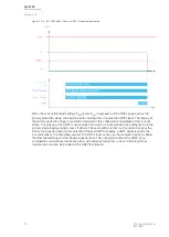
No load
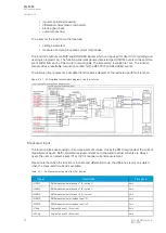
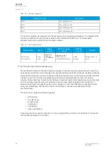
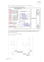
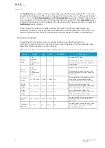
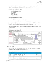
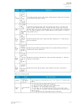
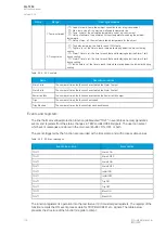
No load signal is activated when the current dips below the "No load current" limit (= 0.2 x I
n
)" for
longer than ten milliseconds. If the current increases from this situation up to the "Heavy overloading"
limit (> 1.3 x
I
n
), the
H
HV inrush de
V inrush dettection
ection and LLV inrush de
V inrush dettection
ection signals are activated. If the measured
current is between the "No load current" limit and the "Nominal current" limit, the
LLoad normal
oad normal signal is
activated. If the measured current is between the "Nominal" and the "Heavy overloading" currents, the
Ov
Overloading
erloading signal is activated.
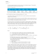
These signals can be used for multiple purposes: information, transformer-related logics, and
monitoring. A constant, long-lasting heavy overloading can cause oil ageing in the transformer, and
thus more frequent maintenance is recommended to prevent possible problems in the transformer.
Settings and signals
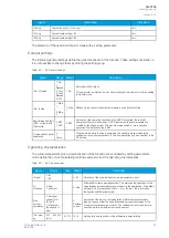
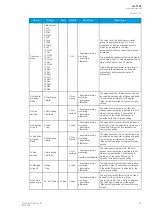
The settings of the transformer status monitoring function are mostly shared with other
transformer protection functions in the transformer module of the device. The following table shows
these other functions that also use these settings.
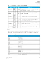
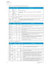
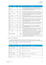
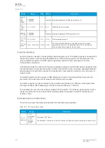
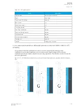
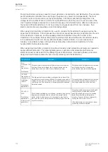
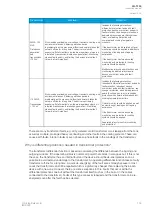
Table. 5.3.8 - 70. Settings of the transformer status monitoring function and how they are shared by other protection functions.
Name
Range
Step
Default
Functions
Description
TRF LN
mode
1: On
2: Blocked
3: Test
4: Test/Blocked
5: Off
-
1: On
-
Set mode of MST block.
This parameter is visible only when
Allow
setting of individual LN mode is enabled in
General menu.
TRF LN
behaviour
1: On
2: Blocked
3: Test
4: Test/Blocked
5: Off
-
-
-
Displays the mode of MST block.
This parameter is visible only when
Allow
setting of individual LN mode is enabled in
General menu.
Transformer
nominal
0.1...500.0MVA 0.1MVA 1.0MVA All
The nominal MVA of the transformer. This
value is used to calculate the nominal
currents onf both the HV and the LV side.
HV side
nominal
voltage
0.1…500.0kV
0.1kV
110.0kV All
The HV side nominal voltage of the
transformer. This value is used to calculate
the nominal currents of the HV side.
LV side
nominal
voltage
0.1…500.0kV
0.1kV
110.0kV All
The LV side nominal voltage of the
transformer. This value is used to calculate
the nominal currents of the LV side.
Transformer
Zk%
0.01…25.00%
0.01%
3.00%
Info
The transformer's short-circuit impedance in
percentages. Used for calculating short-
circuit current.
Transformer
nom. freq.
10…75Hz
1Hz
50Hz
Info
The transformer's nominal frequency. Used
for calculating the transformer's nominal
short-circuit inductance.
A
AQ
Q-T256
-T256
Instruction manual
Version: 2.06
90
© Arcteq Relays Ltd
IM00028
Summary of Contents for AQ-T256
Page 1: ...AQ T256 Transformer protection IED Instruction manual...
Page 2: ......

