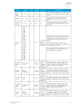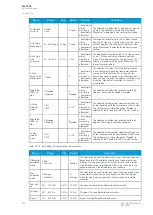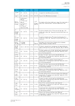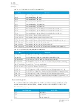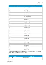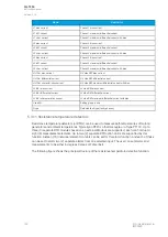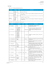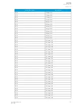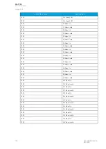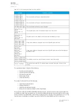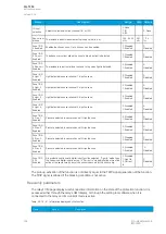
Name
Description
L1 bias current
Phase L1 bias current
L1 diff. current
Phase L1 maximum differential current
L1 char. current
Phase L1 maximum differential current with bias
L2 bias current
Phase L2 bias current
L2 diff. current
Phase L2 maximum differential current
L2 char. current
Phase L2 maximum differential current with bias
L3 bias current
Phase L3 bias current
L3 diff. current
Phase L3 maximum differential current
L3 char. current
Phase L3 maximum differential current with bias
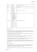
HV I0d> bias current
HV side REF bias current
HV I0d> differential current
HV side REF differential current
HV I0d> characteristics current
HV side REF maximum differential current with bias
LV I0d> bias current
LV side REF bias current
LV I0d> differential current
LV side REF differential current
LV I0d> characteristics current
LV side REF maximum differential current with bias
Used SG
Setting group in use
Ftype
Detected fault type (faulty phases)
5.3.11 Resistance temperature detectors
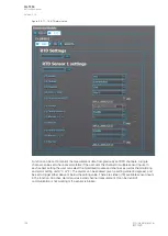
Resistance temperature detectors (or RTDs) can be used to measure both temperatures of motors/
generators and ambient temperatures. Typically an RTD is a thermocouple or of type PT100. Up to
three (3) separate RTD modules based on an external Modbus are supported; each can hold up to
eight (8) measurement elements. Up to two (2) separate RTD option cards are supported by this
function. Sixteen (16) individual element monitors can be set for this alarm function, and each of those
can be set to alarm two (2) separate alarms from one selected input. The user can set alarms and
measurements to be either in degrees Celsius or Fahrenheit.
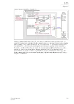
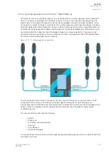
The following figure shows the principal structure of the resistance temperature detection function.
A
AQ
Q-T256
-T256
Instruction manual
Version: 2.06
142
© Arcteq Relays Ltd
IM00028
Summary of Contents for AQ-T256
Page 1: ...AQ T256 Transformer protection IED Instruction manual...
Page 2: ......

