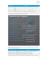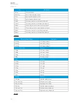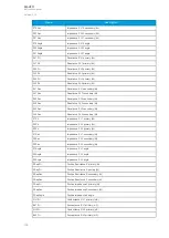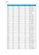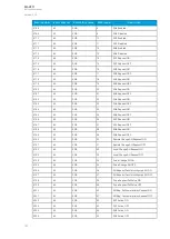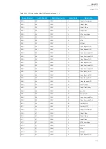
The function registers its operation into the last twelve (12) time-stamped registers. The register of the
function records the ON event process data for START, TRIP or BLOCKED. The table below
presents the structure of the function's register content.
Table. 5.3.11 - 81. Register content.
Date
and time
Event
code
>/< Mag#
Mag#/Set#
Trip time
remaining
Used SG
dd.mm.yyyy
hh:mm:ss.mss
8576-8637
Descr.
The numerical value
of the magnitude
Ratio between the measured
magnitude and the pick-up setting
0
ms...1800s
Setting group
1...8 active
5.4 Control functions
5.4.1 Setting group selection
All relay types support up to eight (8) separate setting groups. The Setting group selection function
block controls the availability and selection of the setting groups. By default, only Setting group 1
(SG1) is active and therefore the selection logic is idle. When more than one setting group is enabled,
the setting group selector logic takes control of the setting group activations based on the logic and
conditions the user has programmed.
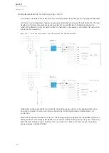
The following figure presents a simplified function block diagram of the setting group selection function.
Figure. 5.4.1 - 112. Simplified function block diagram of the setting group selection function.
Setting group selection can be applied to each of the setting groups individually by activating one
of the various internal logic inputs and connected digital inputs. The user can also force any of the
setting groups on when the "Force SG change" setting is enabled by giving the wanted quantity of
setting groups as a number in the communication bus or in the local HMI, or by selecting the wanted
setting group from
Control
→
Setting groups. When the forcing parameter is enabled, the automatic
control of the local device is overridden and the full control of the setting groups is given to the user
until the "Force SG change" is disabled again.
A
AQ
Q-V211
-V211
Instruction manual
Version: 2.04
160


