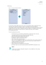
Figure. 4.5 - 36. Programmable mimic indicators section
Programmable mimic indicators can be placed into the mimic to display a text based on the status of a
given binary signal (digital input, logical signal, status of function start/tripped/blocked signals etc.).
When configuring the mimic with the AQtivate setting tool, it is possible to set a text to be shown when
an input signal is ON and a separate text for when the signal is OFF.
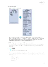
Figure. 4.5 - 37. Logical signals section.
All AQ-200 series units have three different types of logical signals:
• 32 logical input signal status bits; the status of a bit is either 0 or 1.
• 32 logical output signal status bits; the status of a bit is either 0 or 1.
• 64 GOOSE input signal status bits; the status of a bit is either 0 or 1.
• 64 quality bits for GOOSE input signals; the status of a bit is either 0 or 1.
Logical input signals can be used when building a logic with the AQtivate setting tool. The status of a
logical input signal can be changed either from the mimic or through SCADA. By default logical inputs
use "Hold" mode in which the status changes from 0 to 1 and from 1 to 0 only through user input. The
mode of each input can be changed to "Pulse" in which a logical input's status changes from 0 to 1
through user input and then immediately back to 0.
Logical output signals can be used as the end result of a logic that has been built in the AQtivate
setting tool. The end result can then be connected to a digital output or a LED in the matrix, block
functions and much more.
A
AQ
Q-V211
-V211
Instruction manual
Version: 2.04
37


