5-7
5
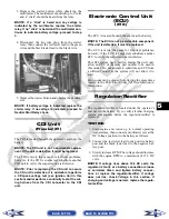
NOTE: The coil is located to the right of the
engine and may be accessed from behind the
right-side seat with the cargo box raised.
2. Connect the red tester lead to the orange wire and
the black tester lead to the blue/white wire.
3. Turn the ignition switch to the ON position. The
meter must show battery voltage.
EFI Sensors/
Components
(XTX)
CRANKSHAFT POSITION (CKP)
SENSOR
To test the CKP sensor, see Stator Coil/Crankshaft
Position (CKP) Sensor (XTX) in this section.
MANIFOLD ABSOLUTE PRESSURE
(MAP) SENSOR
1. Disconnect the MAP connector from the pressure
sensor located on the throttle body.
2. Select DC Voltage on the tester and turn the igni-
tion switch to the ON position.
3. Connect the black tester lead to the black/green
wire and the red tester lead to the brown/white
wire. The meter should read 4.5-5.5 DC volts. If
the meter does not read as specified, check the
ECU connector or wiring.
4. Connect the MAP to the harness; then using Maxi-
Clips, connect the red tester lead to the
brown/white wire and the black tester lead to the
black/green wire. With the engine running at idle
speed, the meter should read approximately 1.5
DC volts.
NOTE: If the meter does not read as specified,
replace the sensor.
Speed Sensor
(XT/XTX)
NOTE: Prior to testing the speed sensor, inspect
the three-wire connector on the speed sensor for
contamination, broken pins, and/or corrosion.
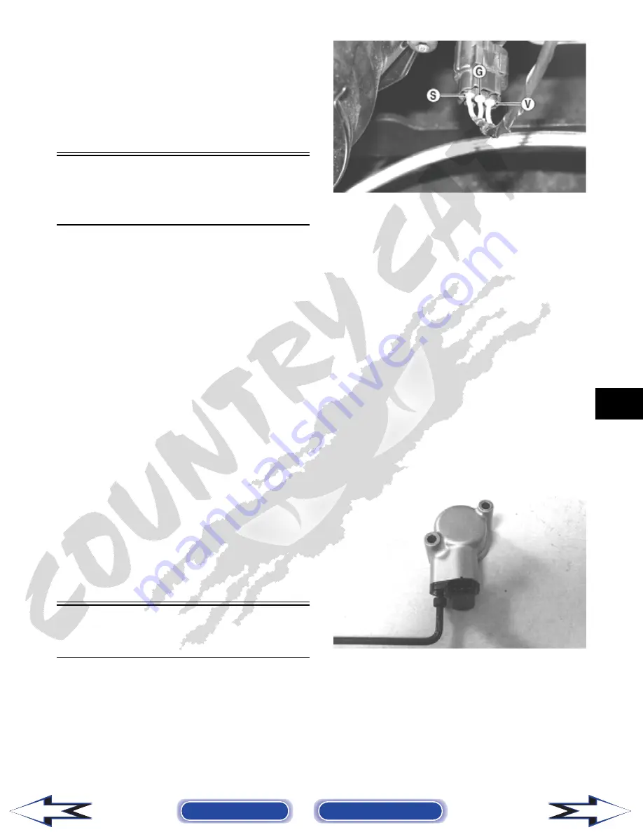
1. Set the meter selector to the DC Voltage position.
2. With appropriate needle adapters on the meter
leads, connect the red tester lead to the voltage
lead (V); then connect the black tester lead to the
ground lead (G).
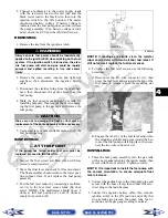
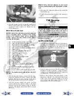
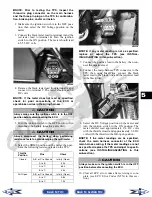
PR279A
3. Turn the ignition switch to the ON position.
4. The meter must show approximately 6 DC volts.
5. Leave the black tester lead connected; then con-
nect the red tester lead to the signal lead pin (S).
6. Slowly move the vehicle forward or backward; the
meter must show 0 and approximately 6 DC volts
alternately.
NOTE: If the sensor tests are within specifica-
tions, the speedometer must be replaced (see Sec-
tion 9).
To replace a speed sensor, use the following proce-
dure.
1. Disconnect the three-wire connector from the
speed sensor harness or from the speed sensor;
then remove the Allen-head cap screw securing
the sensor to the sensor housing.
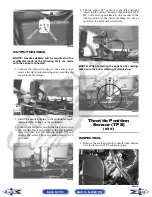
2. Remove the sensor from the sensor housing
accounting for an O-ring.
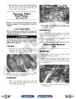
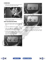
CD070
3. Install the new speed sensor into the housing with
new O-ring lightly coated with multi-purpose
grease; then secure the sensor with the Allen-head
cap screw (threads coated with blue Loctite #242).
Tighten securely.
Back to TOC
Back to Section TOC
Next
Back

