3-19
3
ATV-1085B
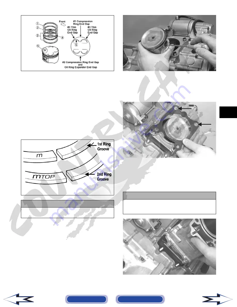
NOTE: Note the direction of the exhaust side of
the piston (5) for correct ring end gap orientation.
B. Install the compression rings (1 and 2) so the
letter on the top surface of each ring faces the
dome of the piston. Rotate the rings until the
ring end gaps are on directly opposite sides of
the piston (see illustration).
NOTE: The ring with the orientation mark (MTOP)
should be installed in the second (middle) groove
and the ring with the orientation mark (M) should
be installed in the first (top) groove.
ATV-1024A
1. Install the piston on the connecting rod making
sure there is a circlip on each side and the open
end of the circlip faces upwards.
NOTE: The piston should be installed so the
arrow points toward the exhaust.
CC032D
2. Place the two alignment pins into position. Place
the cylinder gasket into position; then place a pis-
ton holder (or suitable substitute) beneath the pis-
ton skirt and square the piston in respect to the
crankcase.
CC025D
3. Lubricate the inside wall of the cylinder; then
using a ring compressor or the fingers, compress
the rings and slide the cylinder over the piston.
Route the cam chain up through the cylinder cam
chain housing; then remove the piston holder and
seat the cylinder firmly on the crankcase.
CC024D
4. Loosely install the two nuts which secure the cyl-
inder to the crankcase.
! CAUTION
Incorrect installation of the piston rings will result in
engine damage.
! CAUTION
The cylinder should slide on easily. Do not force the
cylinder or damage to the piston, rings, cylinder, or
crankshaft assembly may occur.
Back to TOC
Back to Section TOC
Next
Back


