3-45
3
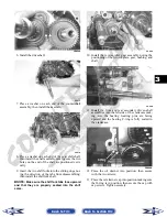
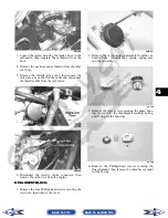
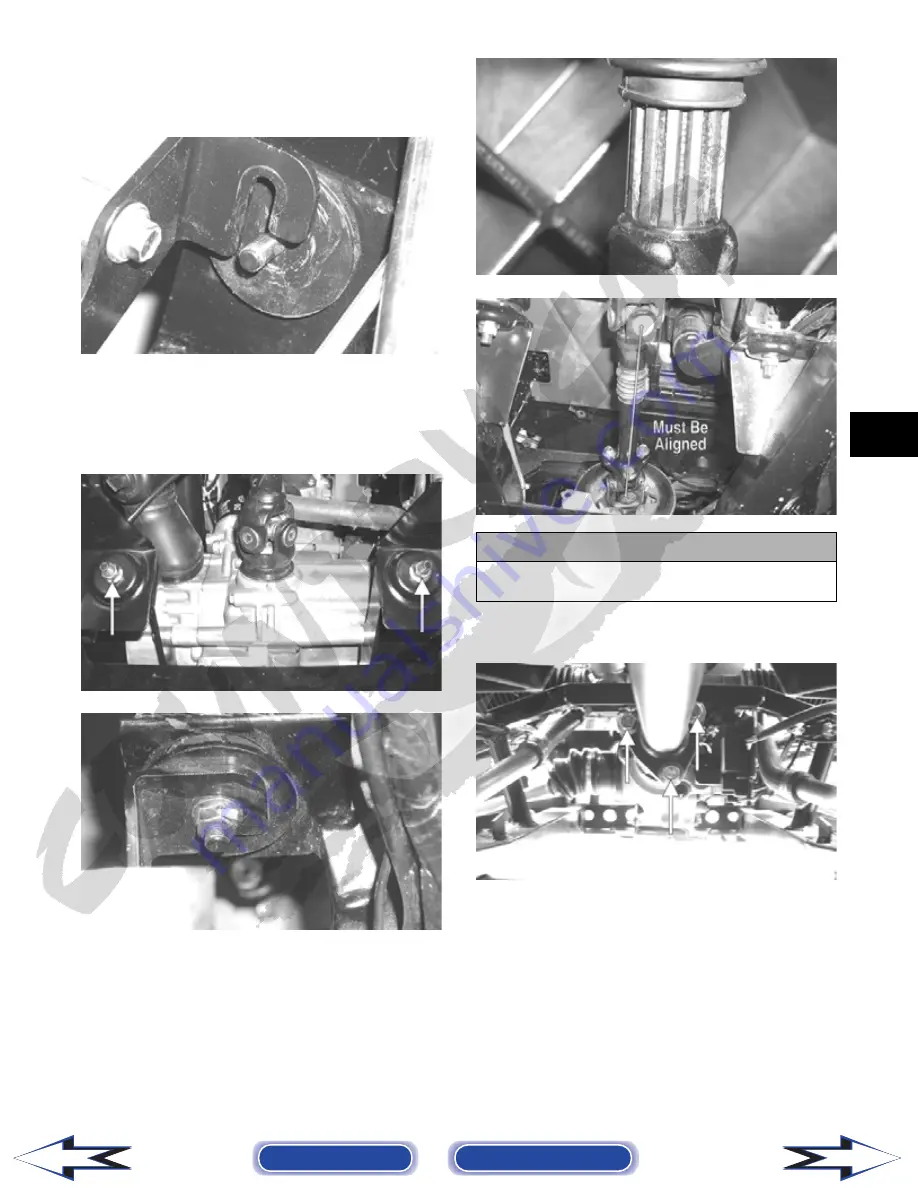
2. Align the rear engine mount studs with the holes in
the frame and slowly lower into place. The front
engine mounting bracket will then slip over the
engine mount studs.
PR146
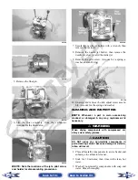
3. Install the flange nuts on the rear engine mount
studs; then secure the front engine mounting
bracket to the front engine mount studs with two
flange nuts. Tighten the four flange nuts to 25
ft-lb.
PR153A
PR147
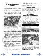
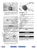
4. Apply multi-purpose grease to the driveshaft
splines; then align the flange marks and slide the
splines into the slip-joints.
PR148
PR151A
5. Install the cap screws securing the drive-line cou-
plers to the drive flanges and tighten to 40 ft-lb.
PR120A
6. Set the exhaust pipe in place; then install the muf-
fler and align the assembly to the engine. Install
two cap screws securing the exhaust pipe to the
cylinder head and tighten to 20 ft-lb.
7. Install the inlet boot on the V-belt housing; then
install the exhaust duct connecting the outlet hous-
ing to the V-belt housing. Tighten all clamps
securely.
! CAUTION
The drive-line yokes must be aligned (timed) or dam-
age will occur to the universal joints and gears.
Back to TOC
Back to Section TOC
Next
Back


