5-12
Front Drive Actuator
NOTE: With the engine stopped and the ignition
switch in the ON position, a momentary “whirring”
sound must be noticeable each time the selector
switch is moved to 2WD and 4WD. Test the switch,
30 amp fuse, and wiring connections prior to test-
ing the actuator.
NOTE: The differential must be in the unlocked
position for this procedure.
VOLTAGE
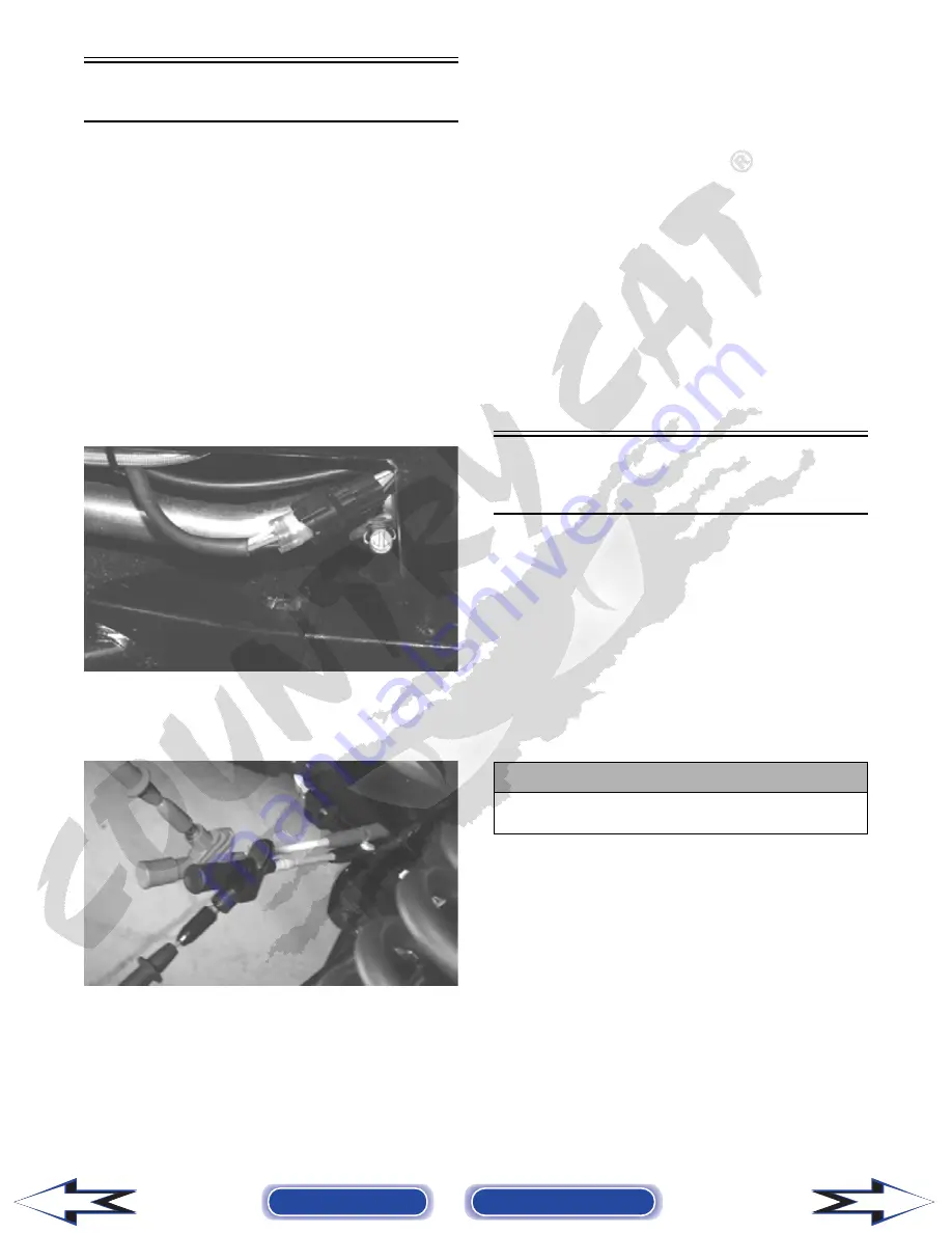
1. Locate the 4-wire connector for the front drive
selector actuator on the frame to the right of the
differential; then connect the red meter lead to the
orange wire using a MaxiClip.
PR293
2. Connect the black lead to the black wire using a
MaxiClip; then select 2WD on the 2WD/4WD
selector switch.
PR295
NOTE: The black tester lead can remain con-
nected to the black wire for the remaining tests.
3. Turn the ignition switch to the ON position. The
meter must show battery voltage.
NOTE: If battery voltage is not shown, trouble-
shoot the 10 amp ignition (IGN) fuse on the power
distribution module, the ignition switch, or the
main wiring harness.
4. Connect the red meter lead to the white/red wire.
The meter must show battery voltage.
5. Select 4WD on the 2WD/4WD selector switch.
The meter must show 0 DC volts.
6. Connect the red meter lead to the white/orange
wire. The meter must show battery voltage.
7. Engage the differential lock. The meter must show
0 DC volts.
NOTE: If the meter does not show 0 DC volts,
rock the vehicle to help engage the differential
lock; then troubleshoot the differential lock switch
(see Differential Lock Switch (XT) in this section).
Stator Coils
(650 cc)
VOLTAGE (Generator Regulated
Output)
1. Set the meter selector to the DC Voltage position.
2. Connect the red tester lead to the positive battery
post; then connect the black tester lead to the nega-
tive battery post.
3. With the engine running at a constant 5000 RPM
(with the headlights on), the meter must show
14-15.5 DC volts.
NOTE: If voltage is lower than specified, test
Charging Coil - No Load.
VOLTAGE
(Charging Coil - No Load)
The connector is the three-wire one on the left side of
the engine just above the centrifugal clutch housing.
NOTE: Test the connector that comes from the
engine.
1. Set the meter selector to the AC Voltage position.
2. Test between the three black wires for a total of
three tests.
! CAUTION
Do not run the engine at high RPM for more than 10
seconds.
Back to TOC
Back to Section TOC
Next
Back


