5-20
NOTE: If any meter reading is not as specified,
replace or adjust the TPS (see INSTALL-
ING/ADJUSTING in this sub-section).
7. Connect the positive lead to the battery; then con-
nect the negative lead.
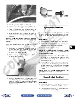
8. Connect the main harness TPS connector to the
TPS; then using MaxiClips, connect the black
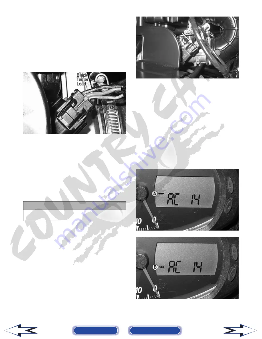
tester lead to the black wire and the red tester lead
to the green/black wire.
PR546A
9. Select the DC Voltage position on the meter and
turn the ignition switch to the ON position. The
meter should read approximately 0.6 DC volts
with the throttle closed and approximately 5.0 DC
volts with the throttle in the full-open position.
NOTE: If the meter readings are as specified,
check the main harness connector at the ECU
main harness wiring. If the meter readings are not
as specified, replace the TPS and adjust to specifi-
cations (see INSTALLING/ADJUSTING in this
sub-section).
10. Clear all ECU error codes after servicing is com-
plete (see ECU Error Codes (550/700 cc) in this sec-
tion).
REMOVING
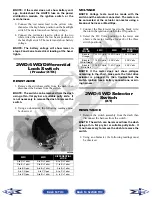
1. Remove the seats and center console; then discon-
nect the three-wire TPS connector plug.
PR533A
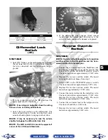
2. Remove the screw securing the TPS to the throttle
body and remove the TPS.
INSTALLING/ADJUSTING
1. Place the TPS into position on the throttle body and
secure with the screw. Do not tighten at this time.
2. Connect the main harness to the TPS.
3. Locate the diagnostic plug under the seat next to
the PDM; then install the Test Plug from Test
Plug/Error Code List onto the plug.
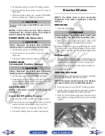
4. Turn the ignition switch to the ON position and
note the position of the TPS indicator icon (A, B,
or C); then adjust the TPS until the TPS icon
appears in the center position (B).
PR542A
PR540A
! CAUTION
Always make sure the ignition switch is in the OFF
position before disconnecting the ECU.
Back to TOC
Back to Section TOC
Next
Back


