6-24
PR239C
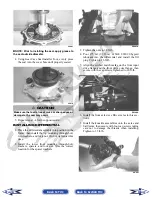
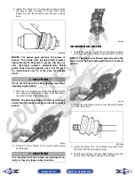
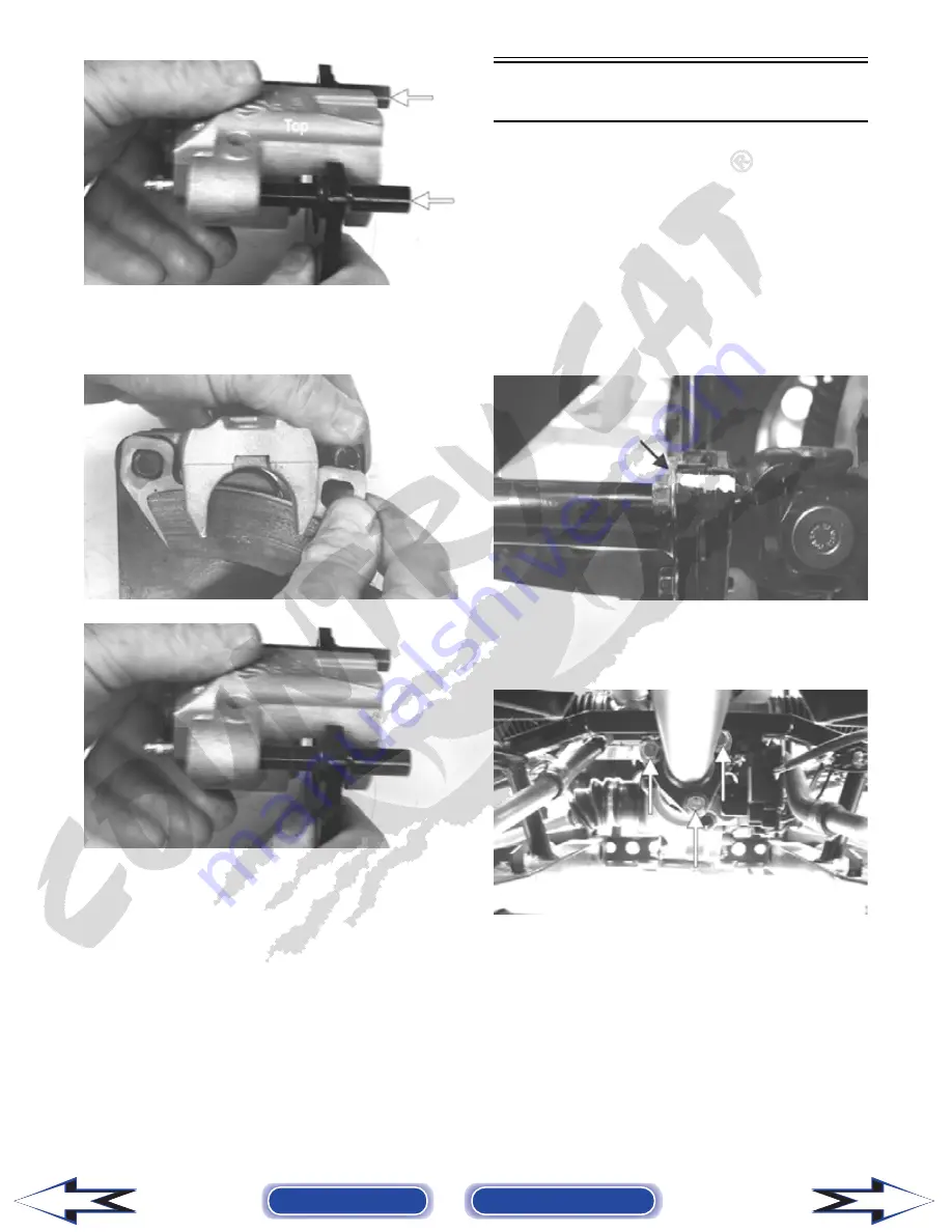
2. Compress the caliper holder toward the caliper and
install the inner brake pad; then install the outer
pad.
PR238
PR239
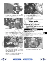
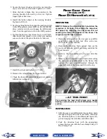
3. Place the brake caliper assembly into position and
secure with the “patch-lock” cap screws. Tighten
the caliper to 20 ft-lb.
4. Place a new crush washer on each side of the brake
hose fitting and install it on the caliper. Tighten to
20 ft-lb.
5. Fill the reservoir; then bleed the brake system (see
Section 2).
6. Install the wheel. Tighten to 45 ft-lb.
7. Remove the vehicle from the support stand and
verify brake operation.
Universal Joints
REMOVING
NOTE: The four universal joints can be accessed
by removing the belly panel. To remove the belly
panel, see Belly Panel in Section 8.
1. Support the vehicle on suitable jack stands ele-
vated high enough to allow working from the
underside of the vehicle.
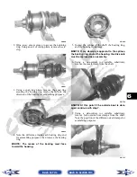
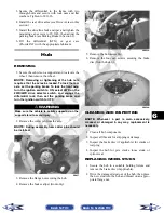
2. To aid in installing, match mark drive-line compo-
nents prior to removing.
PR152A
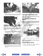
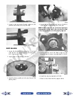
3. Remove the cap screws securing the propeller
shaft flange to the yoke flange on the appropriate
drive-line; then remove the propeller shaft.
PR120A
Back to TOC
Back to Section TOC
Next
Back

