7-6
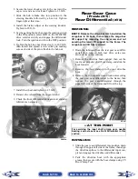
6. Remove the cap screws securing the boot guard to
the lower A-arm.
AF934
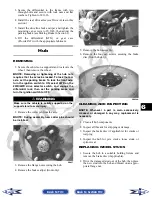
7. Slide the axle out of the knuckle and set aside.
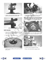
8. Remove the cap screws and lock nuts securing the
knuckle to the A-arms. Discard the lock nuts.
PR220A
NOTE: Never reuse a lock nut. Once a lock nut
has been removed, it must be replaced with a new
lock nut.
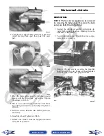
9. Remove the cap screws and lock nuts securing the
A-arms to the frame; then remove the A-arms.
CLEANING AND INSPECTING
NOTE: Whenever a part is worn excessively,
cracked, or damaged in any way, replacement is
necessary.
1. Clean all A-arm components in parts-cleaning sol-
vent.
2. Inspect the A-arm for bends, cracks, and worn
bushings.
3. Inspect the frame mounts for signs of damage,
wear, or weldment damage.
INSTALLING
1. Install the A-arm assemblies into the frame
mounts and secure with the cap screws and new
lock nuts. Finger-tighten only at this time.
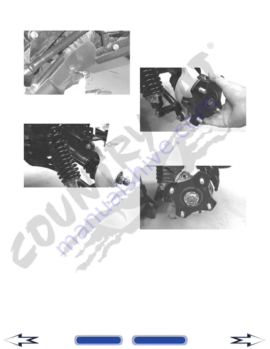
2. Slide the knuckle onto the drive axle and into posi-
tion on the A-arms; then secure the knuckle to the
A-arms with cap screws and new lock nuts.
Tighten to 33 ft-lb.
3. Tighten the hardware securing the A-arms to the
frame mounts (from step 1) to 33 ft-lb.
4. Apply grease on the drive axle splines; then install
the hub assembly onto the drive axle.
PR221
5. Secure the hub assembly with the nut. Tighten to
200 ft-lb.
6. Install a new cotter pin and spread the pin to
secure the nut.
PR196
7. Secure the shock absorber to the frame with a cap
screw and new lock nut. Tighten to 33 ft-lb.
8. Secure the shock absorber to the lower A-arm with
a cap screw and new lock nut. Tighten to 20 ft-lb.
9. Secure the boot guard to the lower A-arm with the
two cap screws. Tighten securely.
10. Install the wheel and tighten to 45 ft-lb.
11. Remove the vehicle from the support stand.
Back to TOC
Back to Section TOC
Next
Back


