3-35
3
PR399A
11. Place the clutch cover/clutch housing assembly
into position on the crankcase; then secure with
the cap screws making sure the different-lengthed
cap screws are in their proper location. Tighten to
8 ft-lb.
12. Place the air intake plate cushion into position;
then install the air intake plate. Tighten the cap
screws (threads treated with a small amount of red
Loctite #271) securely.
CD971
CD970
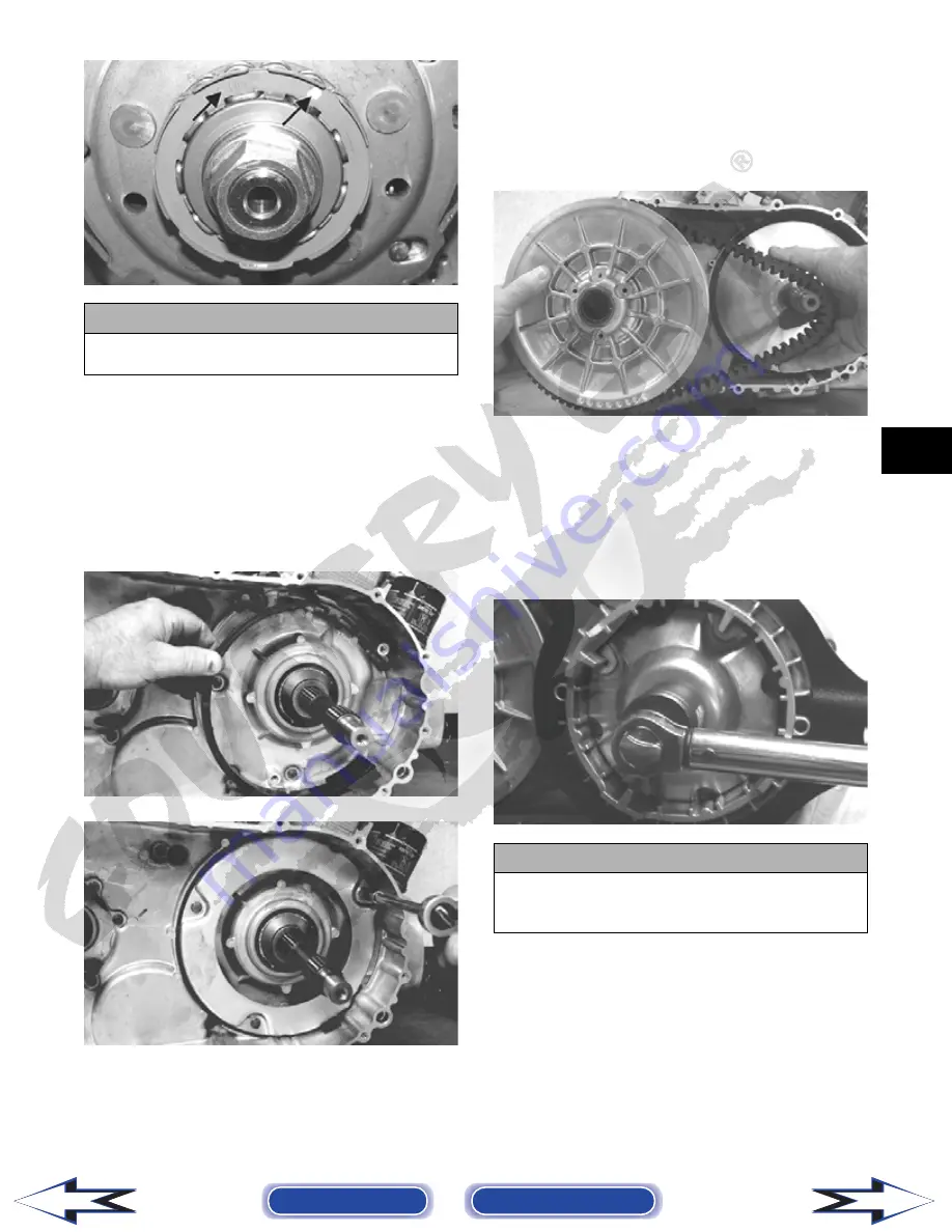
13. Place the driven pulley assembly into position and
secure with the nut. Using Spanner Wrench,
tighten to 80 ft-lb.
14. Slide the fixed drive face onto the shaft.
15. Spread the faces of the driven pulley by threading
a 6 mm cap screw into the threaded boss; then turn
clockwise until pulley faces are opened approxi-
mately 1/2 in.
16. Place the V-belt into position on the driven pulley
and over the front shaft.
PR389
NOTE: The arrows on the V-belt should point for-
ward.
17. Pinch the V-belt together near its center and slide
the spacer and movable drive face onto the drive-
shaft. Secure the drive face with a washer and nut
(coated with red Loctite #271). Using Spanner
Wrench, tighten the nut to 165 ft-lb.
CF261
NOTE: At this point, the cap screw can be
removed from the driven pulley face.
18. Rotate the V-belt and driven pulley/clutch until the
V-belt is flush with the top of the driven pulley.
19. Place the V-belt cover gasket into position; then
install the cover and secure with the cap screws
making sure the different-lengthed cap screws are
in their proper location. Tighten the cap screws to
8 ft-lb.
! CAUTION
When installed correctly, the green dot (or the word
OUTSIDE) on the one-way clutch is visible.
! CAUTION
Make sure the splines extend beyond the drive face
or a false torque reading and spline damage may
occur.
Back to TOC
Back to Section TOC
Next
Back


