background image

9-2

Hand Brake Lever/

Master Cylinder 

Assembly

NOTE: The master cylinder is a non-serviceable

component; it must be replaced as an assembly.

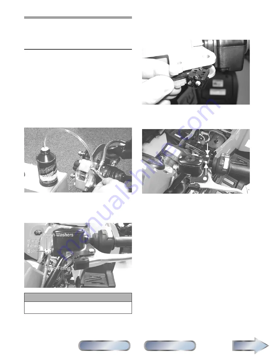
REMOVING

1. Slide a piece of flexible tubing over one of the

wheel bleeder valves and direct the other end into

a container. Remove the reservoir cover; then open

the bleeder valve. Allow the brake fluid to drain

completely.

NOTE: Compressing the brake lever several

times will quicken the draining process.

AF637D

2. Place an absorbent towel around the connection to

absorb brake fluid. Remove the banjo-fitting from

the master cylinder. Account for two crush wash-

ers and a banjo-fitting bolt.

DE059A

3. Remove the snap ring and pivot pin securing the

brake lever to the master cylinder housing; then

remove the brake lever and set aside.

4. Dislodge the brakelight switch from the master

cylinder housing by gently pressing it toward the

pivot pin hole in the housing; then lay it aside

leaving the switch and wiring harness connected.

BC205

5. Remove the clamp screws securing the brake

housing to the handlebar; then remove the assem-

bly from the handlebar.

DE058A

INSPECTING

NOTE: Whenever a part is worn excessively,

cracked, or damaged in any way, replacement is
necessary.

1. Inspect the pin securing the brake lever for wear. 

2. Inspect the brake lever for elongation of the pivot

hole.

3. Inspect the reservoir for cracks and leakage.

4. Inspect the banjo-fitting for cracks and deteriora-

tion and the condition of the fittings (threaded and

compression).

5. Inspect the brakelight switch for corrosion, cracks,

missing or broken mounting tabs, or broken and

frayed wiring.

NOTE: If the brakelight switch is determined to

be not serviceable, see Section 5.

INSTALLING

1. Position the brake housing on the handlebar.

Secure with clamp screws; then tighten securely.

CAUTION

Brake fluid is highly corrosive. Do not spill brake
fluid on any surface of the ATV.

Next

Section

Table of Contents

Manual

Table of Contents

FOR ARCTIC CAT ATV DISCOUNT PARTS CALL 606-678-9623 OR 606-561-4983

www.mymowerparts.com

Summary of Contents for 2010 700 Diesel SD

Page 1: ...entifies personal safety related information Be sure to follow the directive because it deals with the possibility of severe personal injury or even death A CAUTION identifies unsafe practices which may result in ATV related damage Follow the directive because it deals with the possibility of damaging part or parts of the ATV The symbol NOTE identifies supplementary information worthy of particula...

Page 2: ...n Specifications 2 Periodic Maintenance Tune Up 3 Engine Transmission 4 Fuel Lubrication Cooling 5 Electrical System 6 Drive System 7 Suspension 8 Steering Frame 9 Controls Indicators 1 2 3 4 5 6 7 8 9 FOR ARCTIC CAT ATV DISCOUNT PARTS CALL 606 678 9623 OR 606 561 4983 www mymowerparts com ...

Page 3: ...tions 1 2 Tightening Torque General Bolts 1 3 Torque Conversions ft lb N m 1 3 Break In Procedure 1 4 Fuel Oil Lubricant 1 4 Genuine Parts 1 5 Preparation For Storage 1 5 Preparation After Storage 1 5 Manual Table of Contents FOR ARCTIC CAT ATV DISCOUNT PARTS CALL 606 678 9623 OR 606 561 4983 www mymowerparts com ...

Page 4: ...que ft lb N m Front Mounting Bracket Engine 20 27 Engine Mount Upper Frame 35 48 Engine Mount Front Rear Frame 20 27 Front Differential Frame Differential Bracket 38 52 Rear Drive Gear Case Frame 38 52 Input Housing Gear Case Housing 23 31 Output Drive Yoke Nut Output Shaft 72 98 Differential Housing Cover Differential Housing 23 31 Drive Bevel Gear Retaining Nut Secondary Output Shaft 87 118 Seco...

Page 5: ...ntric Camshaft 59 80 Water Pump Engine Block 22 30 CHASSIS COMPONENTS Shift Lever Shift Axle 8 11 SUSPENSION COMPONENTS Front A Arm Frame 50 68 Ball Joint Cap Screw Knuckle 35 48 Shock Absorber Frame 50 68 Shock Absorber Upper A Arm 50 68 SUSPENSION COMPONENTS Rear A Arm Frame 50 68 Shock Absorber Upper Frame 50 68 Shock Absorber Lower Lower A Arm 20 27 Knuckle A Arm 50 68 Type of Bolt ThreadDiame...

Page 6: ...l 42 50 cetane or JP 5 or JP 8 turbine fuel At temperatures above 10 C 14 F use 2 diesel fuel or a biodiesel blend up to 20 At temperatures at or below 10 C 14 F use 1 die sel fuel Diesel fuel with a minimum cetane number below 42 should not be used RECOMMENDED ENGINE OIL The recommended oil to use is an oil which is rated SJ CF under API service classification These oils meet all of the lubricati...

Page 7: ...ther are tight Replace all loose rivets Care must be taken that all calibrated nuts cap screws and bolts are tightened to specifications 7 Fill the cooling system to the bottom of the stand pipe in the filler neck with properly mixed coolant 8 Disconnect the battery cables then remove the battery clean the battery posts and cables and store in a clean dry area 9 Store the ATV indoors in a level po...

Page 8: ...screws making sure all calibrated nuts cap screws and bolts are tightened to specifications 9 Check tire pressure Inflate to recommended pres sure as necessary 10 Make sure the steering moves freely and does not bind CAUTION The ignition switch must be in the OFF position prior to installing the battery or damage may occur to the electrical system CAUTION Connect the positive battery cable first t...

Page 9: ... 2 8 Front Differential Rear Drive Lubricant 2 8 Tires 2 9 Steering Components 2 9 Driveshaft Coupling 2 9 Suspension Shock Absorbers Bushings 2 9 Nuts Cap Screws Screws Bolts 2 9 Injector Timing 2 9 Headlight Taillight Brakelight 2 10 Switches 2 11 Shift Lever 2 11 Frame Welds Racks 2 11 Electrical Connections 2 12 Hydraulic Brake Systems 2 12 Burnishing Brake Pads 2 13 Coolant 2 13 Checking Repl...

Page 10: ...Front Differential Rear Drive Lubricant I R 4 Yrs Transmission Lubricant I I R 4 Yrs Tires Air Pressure I R Steering Components I I R V Belt I l R Suspension Ball joint boots drive axle boots front and rear tie rods differential and rear drive bellows I l R Nuts Cap Screws Screws Bolts I I A Injector Timing I A Headlight Taillight Brakelight I R Switches I R Shift Lever I A L Handlebar Grips R Han...

Page 11: ...the meter reads less than specified voltage charge the battery using the following guide lines A When using an automatic battery charger always follow the charger manufacturer s instructions B When using a constant current battery char ger use the following Battery Charging Chart NOTE If the battery voltage is 11 5 DC Volts or less some chargers may cut off and fail to charge If this occurs connec...

Page 12: ...Air Filter Use the following procedure to remove the filter and inspect and or clean it CLEANING AND INSPECTING FILTER NOTE This ATV is equipped with a dry paper air filter and a cotton fabric safety element DE014A 1 Open the air filter access cover and remove the operator s seat then rotate the air filter housing cover counterclockwise and remove from the filter housing DE006A 2 Remove the dry pa...

Page 13: ...filter element and both elements must be replaced 7 Install the safety element then install the dry paper air filter 8 Check the drain valve in the air filter housing cover for dirt deterioration or poor sealing Clean or replace as required DE015 9 Install the air filter housing cover drain facing downward and lock it in place by turning clock wise DE006A Valve Clearance To check adjust valve clea...

Page 14: ...of the vent hose or fuel return hose Adjusting Throttle Cable To adjust the throttle cable free play follow this proce dure 1 Slide the rubber boot away then loosen the jam nut from the throttle cable adjuster AL611D 2 Turn the adjuster until the throttle cable has proper free play of 1 4 in at the lever ATV 0047C 3 Tighten the jam nut against the throttle cable adjuster securely then slide the ru...

Page 15: ...evel ground and allow it to idle for a few minutes 9 Turn the engine off and wait approximately three minutes 10 Remove the oil level stick and wipe it with a clean cloth DE519D 11 Install the oil level stick and push in firmly 12 Remove the oil level stick the engine oil level should be above the illustrated L mark but not higher than the illustrated F mark DE024A 13 Inspect the area around the d...

Page 16: ...t level stick and wipe it with a clean cloth then check the lubricant level with the level stick DE002A Front Differential Rear Drive Lubricant Check and change the lubricant according to the Peri odic Maintenance Chart When adding or changing the lubricant use approved SAE 80W 90 hypoid gear lube To check lubricant remove each filler plug the lubri cant level should be 1 in below the threads of t...

Page 17: ... pins not damaged or missing Driveshaft Coupling The following drive system components should be inspected periodically to ensure proper operation A Spline lateral movement slop B Coupling cracked damaged or worn Suspension Shock Absorbers Bushings The following suspension system components should be inspected periodically to ensure proper operation A Shock absorber rods not bent pitted or damaged...

Page 18: ... of the socket then insert a new bulb CF132A 3 Insert the socket into the housing and turn it clock wise to secure CHECKING ADJUSTING HEADLIGHT AIM The headlights can be adjusted vertically and horizon tally The geometric center of the HIGH beam light zone is to be used for vertical and horizontal aiming 1 Position the ATV on a level floor so the headlights are approximately 6 1 m 20 ft from an ai...

Page 19: ...ove the seat and left side engine cover 2 With the ignition switch in the ON position loosen jam nut A left hand threads then loosen jam nut C and with the shift lever in the reverse posi tion adjust the coupler B until the transmission is in reverse and the R icon appears on the LCD CF258A 3 Tighten the jam nuts securely then shift the trans mission to each position and verify correct adjust ment...

Page 20: ...ective cap install one end of a clear hose onto one FRONT bleeder screw and direct the other end into a container then while holding slight pressure on the brake lever open the bleeder screw and watch for air bubbles Close the bleeder screw before releasing the brake lever Repeat this procedure until no air bubbles are present AF637D PR377A NOTE During the bleeding procedure watch the reservoir si...

Page 21: ... To properly burnish the brake pads use the following procedure 1 Choose an area large enough to safely accelerate the ATV to 30 mph and to brake to a stop 2 Accelerate to 30 mph then compress brake lever or apply the auxiliary brake to decelerate to 0 5 mph 3 Repeat procedure on each brake system five times until brake pads are burnished 4 Adjust the auxiliary brake if necessary 5 Verify that the...

Page 22: ... V belt cover then using a rubber mallet gently tap on the cover tabs to loosen the cover Remove the cover 3 Remove the cap screw securing the drive clutch to the flywheel stub axle then remove the nut and lock washer securing the movable drive face to the fixed drive hub DE093A DE095 4 Remove the movable drive face using care to keep the face plate tight against the drive face to prevent the weig...

Page 23: ...the driven pulley approximately one inch then squeeze the belt together and slide over the fixed drive hub and onto the one way clutch DE098A 3 Pinch the V belt together near its center and slide the movable drive face onto the drive hub Secure the drive face with a nut threads coated with red Loctite 271 Tighten the nut to 85 ft lb DE483 NOTE At this point the cap screw can be removed from the fi...

Page 24: ...h remove the fuel filter 2 Apply a light coat of oil to the seal ring of the new fuel filter then install the filter Tighten until the seal ring contacts the filter head then tighten an additional 3 4 turn DE032D 3 Depress and release the manual primer pump to charge the fuel filter and purge any air from the system DE031A NOTE Cycle the manual primer pump until the lever becomes firm and resistan...

Page 25: ...SION TABLE OF CONTENTS Engine Transmission 3 2 Specifications 3 2 700 Diesel Table of Contents 3 3 Troubleshooting 3 80 Manual Table of Contents FOR ARCTIC CAT ATV DISCOUNT PARTS CALL 606 678 9623 OR 606 561 4983 www mymowerparts com ...

Page 26: ...t cold engine 0 20 mm 0 008 in Valve Guide Stem Clearance 0 015 0 060 mm 0 0006 0 0024 in Valve Guide Inside Diameter 7 005 7 020 mm 0 2758 0 2764 in Valve Stem Diameter 6 960 6 990 mm 0 2740 0 2752 in Valve Face Seat Width intake exhaust 1 6 2 0 mm 0 063 0 079 in Valve Spring Free Length min 43 0 mm 1 69 in CAMSHAFT AND CYLINDER HEAD Camshaft Lobe Height min intake exhaust 29 498 mm 1 161 in Cams...

Page 27: ...and right footrests see Section 8 3 Drain the coolant engine oil and transmission lubricant see Section 2 4 From the left side remove the E clip from the shift arm then disconnect the shift linkage from the shift arm Account for a bushing and washer DE064A 5 Disconnect the speed sensor connector from the speed sensor then remove the cap screw securing the engine and main harness ground to the tran...

Page 28: ...ove the fuel inlet and lift pump output hoses from the lift pump Discard four crush washers DE078A 12 Remove the fuel supply and fuel return hoses from the fuel rail DE065A 13 Disconnect the wire connectors from the tempera ture sensor oil pressure sensor gear shift position switch connector and voltage regulator then dis connect the starter solenoid glow plug power wire and the alternator positiv...

Page 29: ...ve the exhaust pipe Account for a steel gasket 18 Place a suitable block between the oil pan and frame member then remove the front engine mount cap screw and nut Account for a flat washer DE089A DE086A 19 Remove the cap screw and nut from the upper right engine mount Account for a flat washer DE088A 20 Remove the nuts and cap screws from the left rear and right rear engine mounts Account for two ...

Page 30: ...f the frame TRANSMISSION NOTE The transmission can be removed for ser vicing without removing the engine To remove the transmission use the following procedure 1 Remove the inner front splash shields foot pegs and forward footwells 2 Remove three cap screws securing the front pro peller shaft to the front differential input coupler 3 Remove four cap screws securing the rear propel ler shaft to the...

Page 31: ...separate the front propeller shaft from the front output drive yoke Top Side Components NOTE For efficiency it is preferable to remove and disassemble only those components which need to be addressed and to service only those components The technician should use discretion and sound judgment NOTE The engine transmission does not have to be removed from the frame for this procedure SPEED GOVERNOR R...

Page 32: ...imately 90 from TDC DE275A 6 Using a suitable holding tool remove the cap screw securing the camshaft drive pulley then remove the pulley DE276 7 Remove the front camshaft support housing then remove the governor flyweight assembly Account for a small O ring CAUTION Failure to rotate the engine away from TDC will leave the flywheel side piston in close proximity to the valves If the camshaft is ro...

Page 33: ...Remove the torque limiter safety cover then remove the torque limiter assembly Account for a copper washer DE252A DE285A DE286A CAUTION Do not break the seal or turn the torque limiter adjuster screw Severe engine damage could occur Next Back Section Table of Contents Manual Table of Contents FOR ARCTIC CAT ATV DISCOUNT PARTS CALL 606 678 9623 OR 606 561 4983 www mymowerparts com ...

Page 34: ...zation will have to be per formed DE291A DE327 DE282 11 Remove the governor fork and governor spring assembly through the opening on the linkage hous ing DE253 DE254 Inspecting 1 Inspect the flyweight assembly for loose pins worn contact points or excessive pivot point wear Next Back Section Table of Contents Manual Table of Contents FOR ARCTIC CAT ATV DISCOUNT PARTS CALL 606 678 9623 OR 606 561 4...

Page 35: ...n securely DE282 2 Using a new copper washer install the torque set ting screw assembly and tighten securely then install the safety cover Make sure the torque lim iter spool engages the limiter fork DE288A 3 Using a new gasket install the intake mani fold throttle control assembly by first connecting the high low speed spring assembly to the throttle control arm then place the manifold and gasket...

Page 36: ...secure with the E clip DE249A 6 Place control spool thrust bearing and thrust washer into the governor flyweight assembly and secure the flyweights with a rubber band then place assembly onto the camshaft with a new O ring Make sure to remove the rubber band DE279A DE531A DE535 DE536 Next Back Section Table of Contents Manual Table of Contents FOR ARCTIC CAT ATV DISCOUNT PARTS CALL 606 678 9623 OR...

Page 37: ...ng an appro priate holding tool tighten the cap screw to 59 ft lb DE262 10 Install the timing belt see Left Side Components in this section 11 Install the valve cover using a new gasket then secure with the ten cap screws and using a criss cross pattern tighten to 6 5 ft lb DE407 12 Install the air filter assembly and connect and secure all intake hoses DE074A 13 Install the front body panel and f...

Page 38: ...om the right front corner of the valve cover DE294A 6 Remove the fuel hoses from the fuel rail then plug or close off the hoses to prevent fuel leakage DE295A 7 Remove eight Allen head and two tamper proof torx head cap screws securing the valve cover then remove the valve cover Account for a gasket and oil return boot DE405B NOTE Tamper proof cap screws can be removed using Torx Head Screwdriver ...

Page 39: ...ff the mounting studs being careful to keep the injector push rods with the injector it was originally installed in DE260C DE529 11 Using an appropriate holding tool remove the cap screw securing the camshaft drive pulley to the camshaft then remove the pulley DE276 12 Remove the camshaft support housing then remove the speed governor flyweight assembly Account for an O ring DE245A Next Back Secti...

Page 40: ...horoughly clean the camshaft in parts cleaning solvent then dry with compressed air 2 Inspect each camshaft journal for scoring heat dis coloring or pitting DE298A 3 Inspect all camshaft lobes for scoring galling flaking or pitting DE298B CAUTION Make sure to support the camshaft while the jour nals are pulled clear of the journal bores or damage to journal bores may occur WARNING Always wear safe...

Page 41: ...rnal diameter Measurement must not be less than minimum specification DE522 DE523 7 Using a micrometer measure and record camshaft intake exhaust and injection lobe height Mea surements must not be less than minimum specifi cations DE527 8 Using an inside micrometer measure the camshaft journal holder diameter Measurement must not exceed the maximum specifications Next Back Section Table of Conten...

Page 42: ...cker arms and supports in the original positions as removed coating all components with clean engine oil Hold components in place with rubber bands DE529 Installing NOTE The flywheel end of the camshaft includes a bolt on eccentric to drive the lift pump If the eccentric has been removed install and tighten the cap screw to 58 ft lb 1 Coat the camshaft journals lobes and camshaft bores in the cyli...

Page 43: ...into the governor flyweight assembly then using a rubber band secure the weights around the control spool DE278A DE531A 5 Apply clean engine oil to the governor assembly and install on the camshaft then hold the fly weight assembly and remove the rubber band Install a new O ring on the camshaft DE535 Next Back Section Table of Contents Manual Table of Contents FOR ARCTIC CAT ATV DISCOUNT PARTS CAL...

Page 44: ...in their respective injectors DE529 DE571 9 Rotate the camshaft until the camshaft lobes are facing away from the rocker arms then secure the rocker arm support with the flat washers and nuts Tighten to 29 ft lb DE260C 10 Install the timing belt see Left Side Components in this section AT THIS POINT If the cylinder head has been removed no more components may be installed prior to installation on ...

Page 45: ...tall the air diverter and connect the air boots Tighten the clamps securely 18 Install the front body then install the front rack see Section 8 UNIT INJECTORS Removing 1 Remove the front rack and front body panel see Section 8 2 Remove the air diverter assembly leaving the air intake boots on the ATV then remove the air filter assembly and mounting bracket DE074A 3 Use duct tape or another suitabl...

Page 46: ...move the injection control rack by carefully dis engaging it from the governor linkage sleeve DE534A 11 Rotate the engine until the injector lobe forces the camshaft follower to its highest position then insert a hardened locking pin into the hole in the injector pump barrel DE404A DE329B CAUTION Do not allow dirt and contaminates to enter the die sel fuel system components Dirt or moisture will c...

Page 47: ...ot to damage the injector tip DE565A 3 Measure the injector nozzle protrusion A Mea surement should be 6 80 7 05 mm 0 268 0 277 in Excessive protrusion may be corrected by installing supplemental washers available in 0 25 mm 0 001 in sizes along with the standard cop per washers B DE566A DE570A 4 Clean the fire ring sealing surface in the cylinder head taking care not to damage the pre combus tion...

Page 48: ... rod into the engine DE571 8 Repeat steps 6 and 7 for the second injector if it was removed 9 Install the unit injector retainer nuts and tighten in five steps to 15 ft lb in 3 ft lb increments DE329 10 Rotate the engine clockwise to compress the injec tor push rod sufficiently to remove the hardened pin then repeat for the second injector DE328 11 Install the injector control rack by first engagi...

Page 49: ...he valve cover with a new gasket and oil return boot Using a crisscross pattern tighten the Allen head cap screws to 6 5 ft lb then tighten the two tam per proof torx head cap screws to 6 5 ft lb DE406 DE405B AT THIS POINT If injectors were serviced static injector timing must be set see Top Side Components in this section Next Back Section Table of Contents Manual Table of Contents FOR ARCTIC CAT...

Page 50: ...on 8 VALVE CLEARANCE ADJUSTMENT NOTE If the engine has been disassembled pro ceed to step 4 If the primary objective is to adjust the valves use the following procedure 1 Remove the front rack and front body panel see Section 8 2 Remove the air filter assembly then disconnect the crankcase ventilator hose and oil pressure switch connector from the right side of the valve cover DE074A DE294A DE077B...

Page 51: ...n the Allen head cap screws to 6 5 ft lb then tighten the two tam per proof torx head cap screws to 6 5 ft lb DE406 DE405B 10 Connect the oil pressure switch connector and the crankcase ventilator hose then install the air filter assembly and secure with the existing hardware Tighten securely 11 Install the front body panel then install the front rack and splash panels see Section 8 STATIC INJECTO...

Page 52: ...ed to TDC index mark A and valves closed DE557A 5 Raise the fuel container above the level of the injector then rotate engine counterclockwise until reference mark D is to the left of the 13 BTDC mark B or until fuel is observed flowing from the bleed hose DE560A DE403A 6 Rotate the engine clockwise and stop immediately when the fuel stops flowing This indicates the beginning of injection Next Bac...

Page 53: ...adjust ment screw For late timing proceed to step B For early timing proceed to step C DE562A B While watching the bleed hose turn the adjust ment screw clockwise until fuel flow stops DE562B C While watching the bleed hose turn the adjust ment screw counterclockwise until fuel flow starts A then clockwise until fuel flow stops B DE562C D Hold the adjustment screw and tighten the jam nut securely ...

Page 54: ...e unit injectors see Top Side Compo nents in this section 5 Remove the lift pump and lift pump push rod see Section 4 6 Rotate the crankshaft to approximately 90 after top dead center ATDC DE240A DE275A 7 Turn the camshaft drive pulley until the camshaft and rocker arms are unloaded all rocker arms in valve closed position 8 Remove the three nuts securing the rocker arm shaft then using rubber ban...

Page 55: ...ve spring compressor remove the valves marking their position for assembly NOTE It is recommended to keep all individual components in a set such as valve valve spring valve keepers spring holders and retainers to aid during assembling DE300 AT THIS POINT If the cylinder head is being removed to allow removal of engine block components no further dis assembling is required Proceed to Cleaning and ...

Page 56: ...7 Remove the exhaust manifold then remove the thermostat housing AT THIS POINT The pre combustion chambers do not have to be removed for general service such as valve replace ment valve seat replacement or normal cylinder head service If the pre combustion chambers must be removed always replace them with new cham bers CAUTION Do not attempt to remove the pre combustion cham bers before removing g...

Page 57: ...heck parallelism of spring ends DE318A 6 Clean valve faces valve seats and valve stems DO NOT use a wire brush on valve stems 7 Using a suitable calipers or outside micrometer measure the valve stem If valve stem measures less than minimum specifications the valve must be replaced DE319 8 Measure the valve guide inside diameter using a suitable micrometer or bore gauge If measure ment is greater t...

Page 58: ...E300 4 Place spring seat valve spring and spring cap into position then using a suitable valve spring com pressor compress the spring and install the valve keepers onto the valve stem DE325A DE301 5 Slowly release the valve spring compressor while making sure the valve keepers engage the groove in the valve stem CAUTION If valves are discolored or pitted or if the seating sur face is worn the valv...

Page 59: ...l into the glow plug bore while slightly shifting the chamber until the alignment tool properly engages the opening in the chamber then completely thread the tool in and tighten securely DE322A 4 If the removal tool was utilized remove it from the chamber Install the pre combustion chamber ring nut and using the Pre Combustion Chamber Ring Nut Tool tighten the ring nut to an initial torque of 72 f...

Page 60: ... plane DE386 C Use steps A and B to measure and record piston protrusion on the other piston D Use the piston with the highest protrusion to select the appropriate gasket from the following chart DE342A DE343A DE341A 2 Make sure the cylinder deck surface is clean and free of all oil grease varnish or coolant DE578 3 Remove all traces of fluid from the cylinder head bolt bores then using an appropr...

Page 61: ...atic injector timing see Top Side Components in this section 13 Install the engine and transmission see Installing Engine Transmission in this section Left Side Components NOTE For efficiency it is preferable to remove and disassemble only those components which need to be addressed and to service only those components The technician should use discretion and sound judgment NOTE The engine transmi...

Page 62: ... crankshaft pulley DE214 7 Remove the timing belt cover noting the position of the short cap screw DE214A 8 Rotate the engine in the direction of rotation clockwise facing the timing belt until the refer ence mark A on the camshaft pulley aligns with the reference mark B on the cylinder head DE269A 9 Check that the reference mark C on the timing belt drive pulley aligns with the reference mark D o...

Page 63: ...aligned with the reference mark B on the cylinder head NOTE If the camshaft or crankshaft has been rotated use the following procedure to safely realign the reference marks A Carefully rotate the crankshaft until the refer ence mark C on the timing belt drive pulley is approximately 90 from the reference mark D on the oil pump housing DE275B B Rotate the camshaft to align the reference marks A and...

Page 64: ...ng step 4 two times tighten the tim ing belt idler nut to 29 ft lb 6 Install the timing belt cover and secure with the existing hardware then install the crankshaft pul ley making sure the alignment pin is correctly located DE214B 7 Install the four cap screws and finger tighten then install a suitable holding fixture DE213 8 Apply blue Loctite 243 to the crankshaft pulley retaining cap screw and ...

Page 65: ...iceable com ponent If it is defective it must be replaced as an assembly Installing 1 Make sure all mating surfaces are free of any gas ket material sealant or residue 2 Using a new gasket install the water pump onto the engine and secure with the four cap screws Tighten to 22 ft lb DE267 3 Install the timing belt see Left Side Components in this section 4 Fill the cooling system with coolant see ...

Page 66: ...p install a new oil seal proceed to Installing Installing 1 Clean all gasket material from the surface of the engine block 2 Make sure the oil pump drive key in the crankshaft is in the 3 o clock position then locate the oil pump inner rotor keyway in the 3 o clock position as viewed from the crankshaft seal DE265A DE237A 3 Install two alignment bolts in the engine block then install a new oil pum...

Page 67: ...t B then remove the alternator drive belt DE519C DE103C 4 Remove the adjuster cap screw and pivot bolt and remove the alternator Servicing NOTE The alternator regulator is not a service able part therefore it must be replaced as an assembly Installing 1 Place the alternator regulator into position on the engine then secure with the existing hardware Do not tighten at this time 2 Place the alternat...

Page 68: ...l remove the fixed drive face clutch hub DE099A 3 Remove two cap screws securing the starter to the V belt housing then remove the starter DE102A 4 Remove the PTO flywheel then remove four countersunk cap screws securing the V belt hous ing to the engine block and remove the V belt housing DE109 DE114A Inspecting 1 Inspect the V belt housing for cracks elongated mounting hoses or loose alignment p...

Page 69: ...ing suitable insulated gloves place the heated ring gear onto the flywheel then gently tap the gear down until firmly seated DE594 Installing 1 Using a new gasket secure the V belt housing to the engine block with the four countersunk cap screws tightened to 25 ft lb then install the fly wheel PTO shaft on the crankshaft and using the pattern shown tighten the five cap screws to 40 ft lb DE114A DE...

Page 70: ...her on each end DE122A 6 Remove the nut securing the shift cam detent stop per spring assembly then remove the assembly and account for a spring and washer DE123 7 Remove the speed sensor housing then remove the snap ring securing the rotor and remove the rotor Account for two alignment pins a gasket and two snap rings DE126A 8 From the right side remove the cap screws secur ing the transmission h...

Page 71: ...ote the location of the bearing alignment pin on the front output driveshaft bearing DE663D 11 Remove the shift fork shaft B then remove the high low shift fork 12 Remove the shift shaft C and account for two thrust bearing races one thrust bearing and one washer DE138B 13 Remove the low reverse shift fork then remove the input driveshaft D NOTE The shift forks are identical therefore they may be ...

Page 72: ... any damaged seals from the transmission case 18 Remove the snap ring securing the output drive bearing in the right side case then using appropri ate bearing drivers remove the appropriate bear ings DE169 DE170 Disassembling Driveshaft Drive Bevel Assembly NOTE Steps 1 18 of the preceding sub section must precede this procedure AT THIS POINT If the drive bevel gear assembly G bearings coun tersha...

Page 73: ...washer bearing and seal DE149 Disassembling Countershaft NOTE Steps 1 21 of the preceding sub sections must precede this procedure 22 Remove the high driven gear then remove the high low shift dog Account for a washer and the high driven gear bearing and bushing DE150A DE191A 23 Remove the thrust washer and countershaft drive gear from the opposite end of the countershaft DE150A DE151 24 Remove th...

Page 74: ...r then rotate and remove the splined low gear retainer DE184 27 Remove the low gear Account for a washer and the low gear bearing and bushing DE155 Inspecting 1 Inspect all shafts for excessive wear worn splines bearing surface discoloration or chipped gears DE158A Next Back Section Table of Contents Manual Table of Contents FOR ARCTIC CAT ATV DISCOUNT PARTS CALL 606 678 9623 OR 606 561 4983 www m...

Page 75: ...galling DE143 DE179 4 Inspect roller bearings for chipping missing roll ers or discoloration DE178 DE185 5 Inspect drive and driven bevel gears for proper tooth contact chipping or discoloration of gear teeth worn or chipped splines and bearing smoothness DE657 Next Back Section Table of Contents Manual Table of Contents FOR ARCTIC CAT ATV DISCOUNT PARTS CALL 606 678 9623 OR 606 561 4983 www mymow...

Page 76: ...0 Inspect shift cam detent stopper and shift cam detent for worn rollers or broken spring DE128 11 Inspect bearings for discoloration flaking or roughness and binding when turning 12 Inspect and thoroughly clean all bearing pockets thread bores and plug openings to remove any metal filings or dirt accumulations DE171A 13 Clean all parts to be used for assembling in parts cleaning solvent then dry ...

Page 77: ...reverse driven gear bushing and bearing DE185A 4 Install the reverse driven gear onto the bearing then secure with a splined washer and snap ring NOTE Always install snap rings with the flat sharp side away from the washer DE186 5 Install the reverse shift dog and splined bushing onto the shaft then secure with a snap ring DE187A 6 Install the countershaft drive gear and thrust washer 7 Install th...

Page 78: ...t gear tooth contact If only the secondary output driven gear or shaft are replaced proceed to Correcting Backlash in this sub section DE655A DE659A 1 Install a new bearing A onto the secondary driven shaft B making sure the bearing locating groove is directed away from the driven gear splines AT THIS POINT If the drive bevel gear assembly or secondary output shaft assemblies were disassembled use...

Page 79: ... as this procedure may have to be repeated 5 Place the assembled shaft into the left crankshaft case then lightly coat the gear teeth with machin ist s lay out dye Rotate the shafts through several rotations in both directions Gear contact should extend from the root to the top of the gear teeth DE657A 6 To adjust tooth contact use the following chart to correctly shim the secondary bevel drive ge...

Page 80: ...ure it and install a thinner shim NOTE Continue to remove measure and install until backlash measurement is within tolerance Note the following chart After backlash and tooth contact are within specifica tions apply red Loctite 271 to the driveshaft threads and driven output shaft threads then using new nuts tighten the output shaft nut to 80 ft lb and the output drive yoke nut to 72 ft lb Assembl...

Page 81: ... output driveshaft aligning the front bearing alignment ring with the groove in the gear case and rotate the bearing to locate the bear ing anchor pin in the slot then align the groove in the rear bearing with the case groove and install the C ring DE135A DE663D 7 Apply a thin layer of Three Bond Sealant to the mating surface of the right side gear case then make sure that the alignment pins and w...

Page 82: ...g and secure with the cap screws Tighten securely DE126 DE125 10 Install the gear shift cam plate cam arm stopper and gear shift sub shaft as shown making sure to align the timing marks Tighten all fasteners securely DE121A 11 Using a new gasket install the shift shaft housing and secure with existing cap screws then install the shift arm aligning the mark with the slot Tighten all fasteners secur...

Page 83: ...y it is preferable to remove and disassemble only those components which need to be addressed and to service only those components The technician should use discretion and sound judgment ENGINE BLOCK ASSEMBLY Removing 1 Remove the engine transmission assembly see Removing Engine Transmission in this section 2 Separate the transmission and V belt housing from the engine see Right Side Components in...

Page 84: ...rotrusion above the cylinder deck plane DE386 C Using the same procedure measure and record the second piston protrusion D Mark the piston with the highest protrusion and record that value for use later in this section DE390A 9 Mark the pistons connecting rods and connecting rod caps for installing purposes then rotate the crankshaft so that one connecting rod is at bot tom dead center BDC DE580 N...

Page 85: ... Attach the connecting rod cap with bearing inserts and loosely install the cap screws keeping the assemblies together DE602 13 Remove the two cap screws from the second con necting rod cap and remove the cap Account for one bearing insert DE600 14 Carefully rotate the crankshaft 180 then gently push the piston connecting rod assembly from the cylinder bore CAUTION The connecting rod and connectin...

Page 86: ...ressure away from the crankshaft until the bearing cap is free of the engine block Account for a bearing insert for each cap and two thrust bearing inserts for the flywheel end bearing cap DE336A DE346A 19 Carefully lift the crankshaft from the main bearing saddles and set the crankshaft aside DE376 NOTE The crankshaft should be supported in the three main bearing journal locations or stood on the...

Page 87: ...ate thread taps clean up the main bearing and cylinder head cap screw thread bores DE339 DE349 4 Install main bearing caps into their appropriate saddles then finger tighten the cap screws DE605 5 Make sure the cylinder deck plane is completely free of all gasket material carbon and sealant then using a precision straight edge and feeler gauge check for cylinder deck trueness Maxi mum variation mu...

Page 88: ...n then rinse with hot water and dry with compressed air 7 Using a cylinder bore gauge or suitable snap gauge and micrometer measure the cylinder bore at three locations taking measurements at 45 intervals If the cylinder is found to be 72 050 mm 2 836 in or greater at any measurement point the cylin der s must be bored Oversized pistons rings are available in 0 50 mm 0 020 in and 1 00 mm 0 039 in ...

Page 89: ...ecifications DE360 DE363 DE362 NOTE Undersized connecting rod and main bearings are available in 0 25 mm 0 010 in and 0 50 mm 0 020 in sizes Use of undersized bear ings will require the crankshaft journals to be machined to the correct size by a qualified machine shop 12 Lightly coat the crankshaft journals with clean oil If no machining is required set aside until assem bly WARNING Always wear sa...

Page 90: ...kshaft main bearing journals and record the measurements DE619 16 Subtract the crankshaft journal measurement from the corresponding main bearing bore The clear ance must be within specifications DE609A DE614A CAUTION Always support the crankshaft equally at the main bearing journals or stand the crankshaft on the fly wheel end Do not drop or strike the crankshaft or engine damage caused by cranks...

Page 91: ...s recommended that only a qualified machine shop replace bushings 21 Examine the connecting rods for nicks gouges discoloration and stress lines DE623 22 Examine the piston pin bushing for galling or dis coloration If either condition exists replace the bushing or connecting rod DE623A 23 Measure the piston pins making sure to keep them with their respective piston connecting rod The piston pins m...

Page 92: ...s after machining to insure no filings or metal chips are present Blow out all oil galleys with compressed air Installing 1 Mount the engine block on a suitable engine stand then install the upper main bearing inserts into the main bearing saddles making sure the oil holes in the inserts are aligned with the oil galleys in the saddles and the locating tabs are oriented in the reliefs Class Cylinde...

Page 93: ...en carefully install the crank shaft into the engine block DE620A 5 Thoroughly coat the lateral seals with oil soluble grease then install them in the front and rear main bearing caps DE431A 6 Using Main Bearing Seal Installation Tool or 0 07 mm 0 003 in shim stock as shown slide the main bearing cap into position in the main bearing saddle being careful to keep the seals from sliding out of place...

Page 94: ...the ring in the cylinder bore and using a piston turned upside down push the ring down 25 mm 1 0 in into the piston bore DE374 13 Using an appropriate thickness gauge measure the ring end gap End gap must be according to speci fications DE375 NOTE If ring gap is less than specified install the ring in a soft jawed vise and use a fine flat file to file the ends of the ring checking end gap fre quen...

Page 95: ... 15 Remove the connecting rod caps keeping bearing inserts in place then position the rings on the pis tons as shown in the following illustration 0742 253 16 Apply clean engine oil to the rings and cylinder wall then using a suitable ring compressor com press the rings sufficiently to install the piston in the cylinder DE392 17 Rotate the crankshaft so the crankshaft rod journal corresponding to ...

Page 96: ...l the oil pump see Section 4 24 Install the water pump see Section 4 25 Install the cylinder head see Top Side Compo nents in this section 26 Trim off the excessive material and cover the ends of the lateral seals with RTV Silicone then place a new oil pan gasket in place making sure to prop erly align the gasket with the oil sump and return galleys DE440B WARNING NEVER force the piston into the c...

Page 97: ...b DE442A 30 Install the coolant bypass hose and secure with the support clamps and two Allen head cap screws to the two hollow studs then secure the bypass hose to the fittings with the hose clamps Tighten securely 31 Install a new crankshaft seal in the rear engine seal flange then apply a small amount of RTV Silicone to the extended ends of the lateral seals DE497A 32 Apply a liberal coat of oil...

Page 98: ...t housing and tighten the mounting cap screws to 25 ft lb DE114A 2 Using a new gasket install the transmission into the V belt housing and secure with five cap screws Do not tighten at this time DE113A 3 Install the engine to transmission mounting plate and cap screws then tighten the cap screws from step 2 and from this step to 35 ft lb DE487 4 Install the PTO flywheel onto the crankshaft and sec...

Page 99: ...nt propeller shaft into the front output yoke DE084B 3 Align and connect the rear propeller shaft to the rear output drive flange and secure with four cap screws then align and secure the front propeller shaft to the differential input flange DE081A 4 Install the front mounting bracket onto the engine and secure with four cap screws Tighten to 20 ft lb DE083A 5 Raise the front of the engine and in...

Page 100: ...g a new O ring then connect the throttle cable and thread the throttle cable housing into the bracket DE091A DE080A 9 If removed install the fuel filter bracket onto the frame and tighten the mounting hardware securely DE032 10 Install the exhaust pipe and gasket and secure with two copper nuts Do not tighten the nuts at this time Next Back Section Table of Contents Manual Table of Contents FOR AR...

Page 101: ...regulator then con nect the starter solenoid glow plug power wire and alternator positive wire DE104A DE067A DE077A DE494A 13 Connect the fuel supply and return hoses and secure with the hose clamps DE065A 14 Using new crush washers connect the fuel inlet and lift pump outlet banjo fitting bolts to the lift pump and tighten the banjo fitting bolts securely Next Back Section Table of Contents Manua...

Page 102: ...he coolant filler neck on the thermostat housing and tighten the hose clamp securely then install the upper radiator hose Tighten all hose clamps securely DE073A 19 Install the air diverter and tighten the clamps securely DE515A 20 Secure the engine and main harness grounds to the transmission at the location noted during removal then connect the speed sensor connector to the speed sensor Next Bac...

Page 103: ...23 Pour the recommended coolant engine oil and transmission lubricant into the respective filler necks see Section 2 24 Install the battery and connect the positive battery cable then connect the negative cable 25 Install the seat making sure it locks securely in place Next Back Section Table of Contents Manual Table of Contents FOR ARCTIC CAT ATV DISCOUNT PARTS CALL 606 678 9623 OR 606 561 4983 w...

Page 104: ... not opening 1 Clean vent hose 2 Clean replace hose 3 Replace fuel filter 4 Replace fuel pump 5 See Section 5 Fuel Solenoid Problem Engine stalls easily Condition Remedy 1 Valve clearance out of adjustment 1 Adjust clearance Problem Engine noisy Excessive valve chatter Condition Remedy 1 Valve clearance too large 2 Valve spring s weak broken 3 Rocker arm rocker arm shaft worn 4 Camshaft worn 5 Cam...

Page 105: ...iming incorrect 1 Adjust clearance 2 Replace service seats valves 3 Replace guides 4 Replace arms shafts 5 Replace fuel injector 6 Time injectors Problem Engine runs poorly at high speed Condition Remedy 1 Valve springs weak 2 Valve timing out of adjustment 3 Cams rocker arms worn 4 Air cleaner element obstructed 5 Fuel hose obstructed 6 Fuel pump defective 7 Fuel filter plugged 1 Replace springs ...

Page 106: ...hange oil 9 Time injectors 10 Replace fuel filter Problem Engine overheats Condition Remedy 1 Air filter restricted 2 Oil low 3 Fuel incorrect 4 Oil pump defective 5 Oil circuit obstructed 6 Coolant level low 7 Fan malfunctioning 8 Fan switch malfunctioning 9 Thermostat stuck closed 10 Radiator hoses cap damaged obstructed 1 Clean replace air filter 2 Add oil 3 Drain replace fuel 4 Replace pump 5 ...

Page 107: ...Fuel Filter 4 3 Fuel Solenoid Assembly 4 3 Throttle Cable Free Play 4 4 Fuel Tank 4 4 Fuel Vent Hoses 4 5 Oil Filter Oil Pump 4 5 Testing Oil Pump Pressure 4 5 Liquid Cooling System 4 6 Radiator 4 6 Hoses Thermostat 4 7 Fan 4 7 Water Pump 4 7 Troubleshooting 4 8 Manual Table of Contents FOR ARCTIC CAT ATV DISCOUNT PARTS CALL 606 678 9623 OR 606 561 4983 www mymowerparts com ...

Page 108: ...enters the combustion chamber Fuel in excess of the amount required for any particu lar power setting is directed back into the fuel return side of the fuel rail and routed back to the fuel filter head where it either recirculates or is returned to the fuel tank via the fuel return hose Fuel flow is shut off when the ignition switch is turned to the OFF position A fuel solenoid valve is located on...

Page 109: ...After troubleshooting the fuel solenoid see Section 5 if it is determined that replacement is necessary use the following procedure REMOVING 1 Remove the right front inner splash panel then remove the V belt cooling boot from the V belt housing DE061A 2 Locate the fuel solenoid mounted on top of the fuel filter head then disconnect the spade connec tor from the solenoid DE647B 3 Remove the banjo f...

Page 110: ... adjust throttle cable free play see Section 2 Fuel Tank REMOVING NOTE Fuel tank removal should only be neces sary if the tank is leaking fuel or has been contam inated with water dirt or inadvertently filled with gasoline 1 Remove the seat 2 Remove the rear rack and fenders see Section 8 3 Disconnect the hose from the fuel tank to the lift pump then disconnect the vent hose and fuel return hose 4...

Page 111: ...pect for leakage 6 Install the rear fenders and rack see Section 8 then install the seat making sure it latches securely Fuel Vent Hoses Replace the fuel hoses every two years Damage from aging may not always be visible Do not bend or obstruct the routing of the vent hose or fuel return hose Oil Filter Oil Pump NOTE Whenever internal engine components wear excessively or break and whenever oil is ...

Page 112: ...f the top of the filler neck 4 Install the filler cap on the filler neck and tighten until the cap contacts the stop Radiator REMOVING 1 Drain the coolant at the engine 2 Remove the front rack see Section 8 3 Remove the front bumper and front fender panel see Section 8 4 Remove the upper and lower coolant hoses 5 Remove the cap screws and nuts securing the radi ator to the frame 6 Disconnect the f...

Page 113: ...at 95 C 203 F D If the thermostat does not open or remains open it must be replaced 3 Inspect all coolant hoses connections and clamps for deterioration cracks and wear NOTE All coolant hoses and clamps should be replaced every four years or 4000 miles INSTALLING 1 Place the thermostat and O ring into the thermo stat housing then secure the thermostat housing to the cylinder head with the two cap ...

Page 114: ...ter plugged 1 Replace fuel filter Problem Medium or high speed impaired Condition Remedy 1 Governor spring broken 2 Fuel filter obstructed 3 Throttle cable out of adjustment 1 Replace speed governor spring 2 Replace filter 3 Adjust throttle cable Back Section Table of Contents Manual Table of Contents FOR ARCTIC CAT ATV DISCOUNT PARTS CALL 606 678 9623 OR 606 561 4983 www mymowerparts com ...

Page 115: ...lock Power Distribution Module 5 6 Fuses 5 6 Electronic Speedometer Speed Sensor 5 6 Ignition Switch 5 7 Handlebar Control Switches 5 7 Drive Select Switch 5 8 Front Drive Differential Lock Actuator 5 8 Starter Starter Solenoid 5 9 Starter Relay 5 10 Alternator Regulator 5 10 Neutral Start Front Drive Actuator Start in Gear Differential Lock 2WD Relays 5 11 Headlights 5 11 Taillight Brakelight 5 1...

Page 116: ...eceptacle Connector NOTE This test procedure is for either the recep tacle or the connector VOLTAGE 1 Turn the ignition switch to the ON position then set the meter selector to the DC Voltage position 2 Connect the red tester lead to the red white wire or the positive connector then connect the black tes ter lead to ground 3 The meter must show battery voltage NOTE If the meter shows no battery vo...

Page 117: ...he orange wire then connect the black tester lead to ground AR622D 3 The meter must show battery voltage NOTE If the meter shows no battery voltage troubleshoot the battery fuse switch or the main wiring harness NOTE If the meter shows battery voltage the main wiring harness is good proceed to test the switch component the connector and the switch wiring harness for resistance RESISTANCE Switch Co...

Page 118: ... other meter lead to the switch pin With the meter in the OHMS position the meter should read an open circuit DE650A 3 Remove the meter lead from the switch pin and connect to the thermistor pin then heat the oil and note the temperature and meter readings 4 When the temperature reaches 20 C 68 F the meter should read 1k ohms 5 When the temperature reaches 40 C 104 F the meter should read 460 ohms...

Page 119: ...ter reading is not as specified replace the affected glow plug Fan Motor The connector is the black two prong one located behind the fan assembly NOTE The ignition switch must be in the ON position VOLTAGE Main Harness Connector to Fan Motor 1 Set the meter selector to the DC Voltage position 2 Connect the red tester lead to the black red wire then connect the black tester lead to ground 3 The met...

Page 120: ...han 1 ohm resistance If the meter reads open replace the fuse NOTE Make sure the fuses are returned to their proper position according to amperage Refer to the fuse block cover for fuse placement Electronic Speedometer Speed Sensor NOTE Prior to testing the speed sensor inspect the three wire connector on the speed sensor for contamination broken pins and or corrosion 1 Set the meter selector to t...

Page 121: ...d tester lead to the red wire then connect the black tester lead to the gray wire 9 The meter must show less than 1 ohm 10 With the switch in the OFF position connect the red tester lead to the red wire and the black tester lead to each of the remaining wires The meter must show an open circuit on all wires 11 Connect the red tester lead to the red wire and the black tester lead to the brown wire ...

Page 122: ... the meter shows more than 1 ohm of resistance troubleshoot or replace the switch component the connector or the switch wiring harness Drive Select Switch The connector is the three wire white snap lock one in front of the steering post To access the connector the cover must be removed NOTE Resistance tests should be made with the connector disconnected and on the selector side of the connector RE...

Page 123: ...The 4WD and LOCK icons on the LCD should illuminate NOTE If the voltage readings are as specified and the actuator does not function correctly replace the actuator see Section 6 CF094C Starter Starter Solenoid NOTE The starter is not a serviceable compo nent and must be replaced as an assembly Before replacing the starter troubleshoot the starter volt age starter relay neutral start and start in g...

Page 124: ...meter con tinues to indicate battery voltage proceed to step 4 4 Disconnect the two wire plug from the starter relay then connect the red tester lead to the green wire and the black tester lead to the black wire 5 Depress the starter button and observe the multim eter NOTE If battery voltage is indicated replace the starter relay If no voltage is indicated proceed to Neutral Start Relay check Alte...

Page 125: ...ire and connect the reg ulator control plug in then connect the negative battery cable to the battery 5 Install the left side engine cover and seat making sure the seat latches securely Neutral Start Front Drive Actuator Start in Gear Differential Lock 2WD Relays The relays are identical plug in type located on the power distribution module Relay function can be checked by switching relay position...

Page 126: ...inspect fuses wiring harness connectors and switches VOLTAGE Brakelight NOTE Perform this test on the main harness side of the connector Also the ignition switch should be in the ON position and the brake either foot pedal or hand lever must be applied NOTE Make sure the brake lever hand and brake pedal auxiliary are properly adjusted for this procedure 1 Set the meter selector to the DC Voltage p...

Page 127: ... loose disconnected 1 Charge replace battery 2 Replace switch 3 Replace starter assembly 4 Replace relay 5 Turn on switches 6 Connect tighten repair connections Problem Battery discharges too rapidly Condition Remedy 1 Battery sulfided 2 Electrical system excessively loaded 3 Charging system not charging 1 Replace battery 2 Reduce load 3 Replace alternator tighten alternator belt Problem Battery p...

Page 128: ...rive Actuator 6 2 Front Differential 6 3 Drive Axles 6 16 Rear Gear Case 6 21 Hub 6 21 Hydraulic Brake Caliper 6 22 Troubleshooting Drive System 6 26 Troubleshooting Brake System 6 26 Manual Table of Contents FOR ARCTIC CAT ATV DISCOUNT PARTS CALL 606 678 9623 OR 606 561 4983 www mymowerparts com ...

Page 129: ...nent If it is defective it must be replaced NOTE The actuator will operate only when the ignition switch is in the ON position The front drive actuator is located on the left side of the front drive input housing With the engine stopped and the ignition switch in the ON position a momen tary whirring sound can be heard each time the front drive selector switch is shifted If no sound is heard see S...

Page 130: ...hen tighten the cap screw on the driveshaft side AG926 NOTE It is important to tighten this cap screw while the others are loose to ensure proper seating of the actuator 5 Tighten the remaining cap screws then connect the electrical plug to the main harness 6 Turn the ignition switch to the ON position and check the operation by shifting the selector switch several times 7 Secure the wiring harnes...

Page 131: ...rocedure 7 Remove the two brake calipers Account for the four cap screws AF894D 8 Remove the tie rod cotter pins and discard the pins AF895D 9 Remove the tie rod lock nuts AF896D 10 Remove the upper ball joint cap screws taking care not to strip the threads on the ball joint shaft then using a rubber mallet tap the end of the axle and free it from the knuckle assembly AF628D 11 Pull the steering k...

Page 132: ...s securing the front drive flange to the front drive coupler DE081A 17 Using a T 30 torx wrench remove the three screws securing the front drive actuator to the gear case then remove the actuator AG925 18 Remove the lower differential mounting cap screw Account for a lock nut and washers CAUTION The axle must be supported If the axle is allowed to drop or hang damage to the inner CV joint may occu...

Page 133: ...el The technician should use discretion and sound judgment 1 Using a T 40 torx wrench remove the screws securing the pinion housing PR261A 2 Using a rubber mallet remove the housing Account for a gasket Remove the fork collar and spring Note the location of all the components for assembling purposes CD103 CD106 3 Remove the snap ring then remove the input shaft from the pinion housing CD107 Next B...

Page 134: ...ring making sure the sharp edge of the snap ring faces to the outside AF993 AF994 2 Install the input shaft seal making sure it is flush with the edge of the housing 3 Lubricate the input shaft splines with High Perfor mance 2 Molybdenum Disulphide Grease NOTE Any time drive splines are separated clean all splines with parts cleaning solvent and dry with compressed air then lubricate with rec omme...

Page 135: ... for the cou pler fork and spring KX209 2 Using a T 40 torx wrench remove the cap screws securing the gear case cover Account for and make note of the ID tag location for assembling purposes KX173 3 Using a plastic mallet tap lightly to remove the differential cover Account for an O ring KX174 NOTE If the cover is difficult to remove pry on the cover in more than one recessed location 4 Remove the...

Page 136: ...g the 48 mm Internal Hex Socket remove the lock collar securing the pinion gear assembly NOTE On a front differential the lock collar has right hand threads On a rear gear case the lock collar has left hand threads CC875 CC876 8 Using the Pinion Gear Shaft Removal Tool and a hammer remove the pinion gear from the gear case housing Next Back Section Table of Contents Manual Table of Contents FOR AR...

Page 137: ...tions shims are nominally 1 5 mm 0 060 in thick 738 268B A Cover Side add value A on the gear case hous ing to value B on the gear case cover then add 1 5 mm 0 060 in This will give you the proper shim thickness NOTE When shimming a rear gear case add value A to value B B Gear Case Side install a 1 3 1 4 mm 0 050 0 055 in shim and tighten the bolts to 25 31 ft lb Verify backlash to be within a ran...

Page 138: ...reads CC890 4 Place a punch on the edge of the lock collar in the oil gallery area then using a hammer stake the lock collar to ensure that the collar will remain securely tightened CC891 5 Install the shift fork shaft w spring into the gear housing making sure the shaft O ring is positioned to the inside CC892 6 Install the shift fork assembly making sure the fork leg is facing upward Apply a sma...

Page 139: ...ward the ring gear Install the ring gear in the housing then install the outside shim with the chamfer side of the shim toward the ring gear NOTE The spider and ring gear assembly must be replaced as a complete unit CC896 CC897 KX178 9 Assemble the fork and sliding collar into the cover assembly then install left bearing flange bearing assembly and seat it firmly into the cover CF266A Next Back Se...

Page 140: ... the needle bearing is rarely necessary Avoid removing the needle bearing unless the bearing is clearly damaged NOTE This procedure can be performed on a rear gear case 1 Place a 1 4 in drill bit on the inside surface of the needle bearing against the bottom side then drill through the pinion shaft needle bearing housing CC885 2 Using a propane torch heat the area surrounding the needle bearing to...

Page 141: ...he oil gallery area then using a hammer stake the lock collar to ensure that the collar will remain securely tightened CC891 5 Install the pinion housing Removing Installing Axle Seal NOTE This procedure can be performed on a rear gear case 1 Remove the seal using a seal removal tool CC899 2 Using a press remove the bearing CC900 3 Using a press install the new bearing into the housing Next Back S...

Page 142: ...ing hardware DE081A CD859 3 Pour 275 ml 9 3 fl oz of SAE 80W 90 hypoid lubricant into the differential and install the fill plug Tighten to 16 ft lb 4 Install the front drive actuator with the three torx head cap screws then connect the wire con nector to the main wiring harness AG925 5 Install the inner fender panels 6 Install the front axles see Drive Axles in this sec tion 7 Secure the upper A ...

Page 143: ... calipers right side only NOTE Do not allow the brake calipers to hang from their cable hose 6 Slide the hub out of the knuckle and set aside 7 Remove the cap screw and lock nut securing the knuckle to the upper A arm Discard the lock nut NOTE Never reuse a lock nut Once a lock nut has been removed it must be replaced with a new lock nut 8 While holding the drive axle stationary pull the top of th...

Page 144: ...d with a boot kit 3 Inspect the gear case seals for nicks or damage DISASSEMBLING AXLES 1 Using a side cutters or suitable substitute remove the large clamp from the boot CD020 2 Wipe away excess grease to access the retaining ring Using an awl or snap ring pliers remove the circlip CD021 3 Using a snap ring pliers remove the snap ring securing the bearing ring to the shaft Note the direction of t...

Page 145: ... 120 grams of grease The inside joint double offset requires approximately 70 90 grams of grease and the out side bell type requires approximately 35 55 grams When replacing boots use 2 3 of the pack for inside boots and 1 3 of the pack for outside boots 9 Slide the new outside boot onto the shaft with the new clamps positioned as shown Note the differ ent sized clamps from removal NOTE The boot i...

Page 146: ...ces away from the boot CD023 6 Making sure the marks made during disassembling align slide the housing over the bearing ring then completely seat the bearing ring into the housing and install the snap ring NOTE Pull the bearing ring out of the housing until it contacts the snap ring then slide the ring in half way This will purge air from the housing and ensure the bearing is packed properly CD021...

Page 147: ... ATV from the support stand and release the brake lever lock INSTALLING FRONT DRIVE AXLE 1 Position the drive axle in the gear case and steer ing knuckle then insert the upper A arm ball joint into the steering knuckle Secure with a cap screw tightened to 50 ft lb 2 Place the brake hose into position on the upper A arm then secure the lower shock eyelet to the A arm with a cap screw and a new lock...

Page 148: ...e 271 and lock nuts Tighten to 20 ft lb 3 Install the rear drive axles see Drive Axles in this section 4 Install the left side rear A arms see Section 7 Hub REMOVING 1 Secure the ATV on a support stand to elevate the wheel then remove the wheel 2 Remove the cotter pin from the nut NOTE During assembly new cotter pins should be installed KX041 3 Remove the flange nut securing the hub 4 Remove the b...

Page 149: ...he hub nut from step 4 to 200 ft lb then install and spread a new cotter pin making sure each side of the pin is flush to the hub nut CD008 7 Install the wheel and tighten to 45 ft lb 8 Remove the ATV from the support stand Hydraulic Brake Caliper REMOVING DISASSEMBLING 1 Secure the ATV on a support stand to elevate the wheel then remove the wheel WARNING Arctic Cat recommends that only authorized...

Page 150: ...r opposite the O ring side and remove the outer brake pad then remove the inner brake pad NOTE If brake pads are to be returned to service do not allow brake fluid to contaminate them PR237A PR238 5 Remove the caliper holder from the caliper and discard the O ring PR239B NOTE The O ring is used for shipping purposes and provides no function in operation 6 Cover the piston end of the housing with a...

Page 151: ...he caliper holder for wear or bending ASSEMBLING INSTALLING 1 Install new seals into the brake caliper housing and apply a liberal amount of DOT 4 brake fluid to the cylinder bore of the housing seals and brake piston PR715 PR717A 2 Press the piston into the caliper housing using hand pressure only Completely seat the piston then wipe off any excessive brake fluid PR711A PR712 3 Apply high tempera...

Page 152: ...ighten to 20 ft lb 8 Fill the reservoir then bleed the brake system see Section 2 9 Install the wheel Tighten to 45 ft lb 10 Remove the ATV from the support stand and ver ify brake operation CAUTION If brake pads become contaminated with brake fluid they must be thoroughly cleaned with brake cleaning solvent or replaced with new pads Failure to do so will result in reduced braking and premature br...

Page 153: ...lace gear s 8 Replace axle 9 Replace axle Problem Braking poor Condition Remedy 1 Pad worn 2 Pedal free play excessive 3 Brake fluid leaking 4 Hydraulic system spongy 5 Master cylinder brake cylinder seal worn 1 Replace pads 2 Replace pads 3 Repair replace hydraulic system component s 4 Bleed hydraulic system correct or repair leaks 5 Replace master cylinder Problem Brake lever travel excessive Co...

Page 154: ...OF CONTENTS Suspension 7 2 Shock Absorbers 7 2 Front A Arms 7 3 Rear A Arms 7 5 Wheels and Tires 7 7 Troubleshooting 7 8 Manual Table of Contents FOR ARCTIC CAT ATV DISCOUNT PARTS CALL 606 678 9623 OR 606 561 4983 www mymowerparts com ...

Page 155: ... rod for nicks pits rust bends and oily residue 3 Inspect all springs spring retainers shock rods sleeves bushings shock bodies and eyelets for cracks leaks and bends INSTALLING 1 Place the shock absorber spring over the shock absorber compress the spring and install the retainer 2 Place bushings and sleeves where appropriate into shock eyelet then install shock with two cap screws and nuts Tighte...

Page 156: ...ap screws securing the ball joints to the knuckle AF628D 8 Tap the ball joints out of the knuckle then remove the knuckle 9 Remove the lower shock absorber eyelet from the upper A arm 10 Remove the cap screws securing the A arms to the frame AF610D 11 Remove the snap ring from the ball joint then remove the ball joint from the A arm WARNING Make sure the ATV is solidly supported on the sup port st...

Page 157: ...emblies into the frame mounts and secure with the cap screws Only fin ger tighten at this time AF610D 3 Route the brake hose through the upper A arm shock absorber mount then secure the hose to the A arm with a cable tie and grommet DE054A 4 Secure the lower eyelet of the shock absorber to the upper A arm Tighten nut to 50 ft lb 5 Secure the A arm assemblies to the frame mounts from step 2 Tighten...

Page 158: ...rt stand to elevate the wheels 2 Pump up the hand brake then engage the brake lever lock 3 Remove the wheel 4 Remove the cotter pin securing the hex nut then remove the hex nut Release the brake lever lock 5 Remove the caliper right side only NOTE Do not allow the brake calipers to hang from their cable hose 6 Remove the cap screws and lock nut securing the shock absorber to the frame and lower A ...

Page 159: ...me 2 Slide the knuckle onto the drive axle and into posi tion on the A arms then secure the knuckle to the A arms with cap screws and new lock nuts Tighten to 50 ft lb 3 Tighten the hardware securing the A arms to the frame mounts from step 1 to 50 ft lb 4 Apply grease on the drive axle splines then install the hub assembly onto the drive axle CD009 5 Secure the hub assembly with the nut Tighten o...

Page 160: ...cracks dents or bends 4 Inspect each tire for cuts wear missing lugs and leaks INSTALLING Install each wheel on its hub Tighten to 45 ft lb NOTE Make sure each wheel is installed on its proper hub as noted in removing the rotation arrow if applicable must indicate forward direc tion of rotation AF612D CHECKING INFLATING 1 Using an air pressure gauge measure the air pres sure in each tire Adjust th...

Page 161: ...operation see Section 2 5 Increase the air pressure in the tires with the small est circumference measurement until all tires are equal in circumference 6 Repeat steps 4 5 as necessary to ensure proper handling Troubleshooting WARNING Do not operate the ATV if tire damage exists Problem Suspension too soft Condition Remedy 1 Spring s weak 2 Shock absorber damaged 3 Shock absorber preload too low 1...

Page 162: ... Toe In 8 6 Front Rack 8 8 Front Bumper Assembly 8 8 Front Body Panel Side Panels 8 8 Footrests 8 11 Belly Panel 8 11 Exhaust System 8 11 Rear Body Panel Rack 8 12 Adjusting Headlight 8 13 Taillight Assembly 8 13 Seat 8 13 Troubleshooting 8 14 Manual Table of Contents FOR ARCTIC CAT ATV DISCOUNT PARTS CALL 606 678 9623 OR 606 561 4983 www mymowerparts com ...

Page 163: ...over assembly forward and lift off 5 Remove the four cap screws securing the handle bar caps and instrument pod bracket to the steering post then move the handlebar out of the way Account for four handlebar caps 6 Remove two cap screws securing the upper steer ing post bearing to the frame Account for two bearings and two housings CD760 7 Using a suitable lift stand raise the ATV enough to remove ...

Page 164: ...s wear or unusual bends 8 Inspect the handlebar grips for damage or wear INSTALLING 1 Place the steering post into position then secure the lower bearing flange to the frame with two cap screws Tighten to 20 ft lb AL600D 2 Place the upper steering post bearings into the housings then position on the steering post and secure the housings to the frame with two cap screws Tighten to 20 ft lb CD760 3 ...

Page 165: ... the handlebar of glue residue oil or any other con taminant 1 Apply a liberal amount of Handlebar Grip Adhe sive to the inside of the grip 2 Slide the grip onto the handlebar until it is fully seated with the smooth part of the grip facing up 3 Wipe off any excess glue then secure the grip with the handlebar plug and end cap Steering Knuckles REMOVING AND DISASSEMBLING 1 Secure the ATV on a suppo...

Page 166: ...secure with the two cap screws Tighten to 35 ft lb AF760D 3 Install the tie rod end and secure with the nut Tighten to 30 ft lb then install a new cotter pin and spread the pin NOTE During assembling new cotter pins should be installed AF759D 4 Apply a small amount of grease to the hub splines PR290A 5 Install the hub assembly onto the splines of the shaft 6 Secure the hub assembly with the nut Ti...

Page 167: ...n the tires or inaccurate measurements can occur CD005 3 Place the ATV in a level position taking care not to push down or lift up on the front end then turn the handlebar to the straight ahead position NOTE When measuring and adjusting there should be a normal operating load on the ATV 4 Measure the distance from the outside edge of each handlebar grip to equal reference points on each side DE047...

Page 168: ...nce between the marks at a height parallel to the belly panel at the front side then record the measurement 10 Push the ATV forward until the marks are parallel to the belly panel on the back side then measure the distance between the marks 11 The difference in the measurements must show 3 2 6 4 mm 1 8 1 4 in toe in the front measure ment 3 2 6 4 mm 1 8 1 4 in less than the rear measurement 12 If ...

Page 169: ... to the frame then remove the bumper CLEANING AND INSPECTING NOTE Whenever a part is worn excessively cracked or damaged in any way replacement is necessary 1 Clean all bumper components 2 Inspect all welds for cracking or bending INSTALLING 1 Place the front bumper assembly into position and install the through bolt Start the lock nut and fin ger tighten only 2 Install the two flange bolts and lo...

Page 170: ...t knob then remove the shift lever pivot axle nut and remove the axle and shift lever Account for a spring and two O rings CD779 CD780A 8 Disconnect four headlight connectors and secure the wires out of the way then disconnect the wires to the front accessory plug CD681 9 Rotate the handlebar to the full left position then lift and slide the panel to the rear and lift the rear up to clear the hand...

Page 171: ... 3 Make sure the rubber grommets and bushings are in place then place the front rack into position and secure with the screws and flange nuts Tighten securely 4 Install one cap screw and flange nut and four plas tic rivets on each side to secure the front fenders to the footwells Tighten the flange nuts securely NOTE If the footwells have been removed see Footrests in this section 5 Install four c...

Page 172: ...eldments for cracks or unusual bends 3 Inspect all tubing for cracks or unusual bends INSTALLING 1 Secure the footrests to the frame with four cap screws and two flange nuts then tighten securely 2 Place the footwells onto the footrests then put the foot pegs in position and secure with two cap screws 3 Install the machine screws and flange nuts secur ing the front and rear fenders to the footwell...

Page 173: ... NOTE The battery does not have to be removed to remove the rear body panel 5 Disconnect the taillight brakelight then remove the fuel tank cap and lift off the rear body panel Install the fuel tank cap NOTE If the front body panel has not been removed the left side and right side panels and the two machine screws must be removed see Front Body Panel Side Panels in this section CLEANING AND INSPEC...

Page 174: ...rt is worn excessively cracked or damaged in any way replacement is necessary 1 Inspect wiring harness three prong connector lens base cap screws and socket for damage 2 Inspect all wires for corroding pinching and cracking 3 Inspect the bulb for wattage voltage and proper operation INSTALLING 1 Place the assembly into position on the frame and secure with torx head cap screws and any washers 2 Ti...

Page 175: ...eplace tires 7 Replace bushings 8 Tighten bolts nuts 9 Replace wheel studs Problem Steering pulling to one side Condition Remedy 1 Tires inflated unequally 2 Front wheel alignment incorrect 3 Wheel hub bearings worn broken 4 Frame distorted 5 Shock absorber defective 1 Adjust pressure 2 Adjust alignment 3 Replace bearings 4 Repair replace frame 5 Replace shock absorber Problem Tire wear rapid or u...

Page 176: ...d bushing worn 7 Rear shock absorber damaged 8 Rear suspension arm nut loose 9 Wheel studs loose missing 1 Replace bearings 2 Replace tires 3 Replace rim 4 Tighten replace lug nut s 5 Tighten nut 6 Replace bushing 7 Replace shock absorber 8 Tighten nut 9 Replace wheel studs Back Section Table of Contents Manual Table of Contents FOR ARCTIC CAT ATV DISCOUNT PARTS CALL 606 678 9623 OR 606 561 4983 w...

Page 177: ...E OF CONTENTS Hand Brake Lever Master Cylinder Assembly 9 2 Throttle Control 9 3 Shift Lever 9 4 Speedometer Tachometer LCD 9 4 Manual Table of Contents FOR ARCTIC CAT ATV DISCOUNT PARTS CALL 606 678 9623 OR 606 561 4983 www mymowerparts com ...

Page 178: ...y it aside leaving the switch and wiring harness connected BC205 5 Remove the clamp screws securing the brake housing to the handlebar then remove the assem bly from the handlebar DE058A INSPECTING NOTE Whenever a part is worn excessively cracked or damaged in any way replacement is necessary 1 Inspect the pin securing the brake lever for wear 2 Inspect the brake lever for elongation of the pivot ...

Page 179: ...e handlebar 2 Slide the grommet out of the lower half of the throttle control then remove the cable from the actuator arm AF676D 3 Remove the cap screw lock washer and washer securing the actuator arm to the throttle control lever AF677D 4 Remove the actuator arm and account for a bush ing Note the position of the return spring for installing purposes AF678D INSTALLING 1 Place the return spring in...

Page 180: ... clip 2 Using a new lock nut B secure the shift rod to the upper shift arm then using two open end wrenches tighten securely AF941A 3 Place the spring into position between the upper shift arm and shift lever then making sure the O rings are in place on the axle secure the shift lever to the arm with the existing axle and nut 4 Check shift lever adjustment see Section 2 then tighten jam nut A secu...

Reviews: