7-4
2. To inspect the swing arm and swing arm axle,
place the swing arm axle and bushings in the
swing arm; then using the flange bolt, rock the
bushings and axle from side to side and up and
down. If excessive play is noted, the bushings,
axle, or swing arm must be replaced. Check for
cracks or broken welds.
3. Remove and clean all pivot bushings, thrust bear-
ings, and pivot axle; then coat all parts with grease
and install in the swing arm pivot.
ASSEMBLING AND INSTALLING
1. Place the swing arm assembly into position in the
frame making sure the swing arm thrust covers are
properly positioned; then install the pivot bolt and
secure with the nut. Tighten to 50 ft-lb.
2. Install the rear shock absorber and secure with the
mounting cap screws and nuts. Tighten to 29 ft-lb.
3. Install the rear axle assembly (see Section 6); then
install the brake caliper and secure with the cap
screws coated with blue Loctite #242. Tighten to
24 ft-lb.
4. Insert the grommet with brake hose and speed sen-
sor wires into the wire holder on the swing arm;
then connect the speed sensor wires to the main
harness.
5. Install the rear hubs and tighten the nuts to 50
ft-lb; then secure with new cotter pins. Install hub
caps.
SP366
6. Install the rear wheels and tighten the nuts to 32
ft-lb; then remove the support stand and lower the
ATV to the floor.
7. Check chain tension (see Section 2) and make sure
the brake functions normally.
Front A-Arms
NOTE: Critical torque specifications are located
in Section 1.
REMOVING
1. Secure the ATV on a support stand to elevate the
front wheels; then remove the wheel on the side
being serviced.
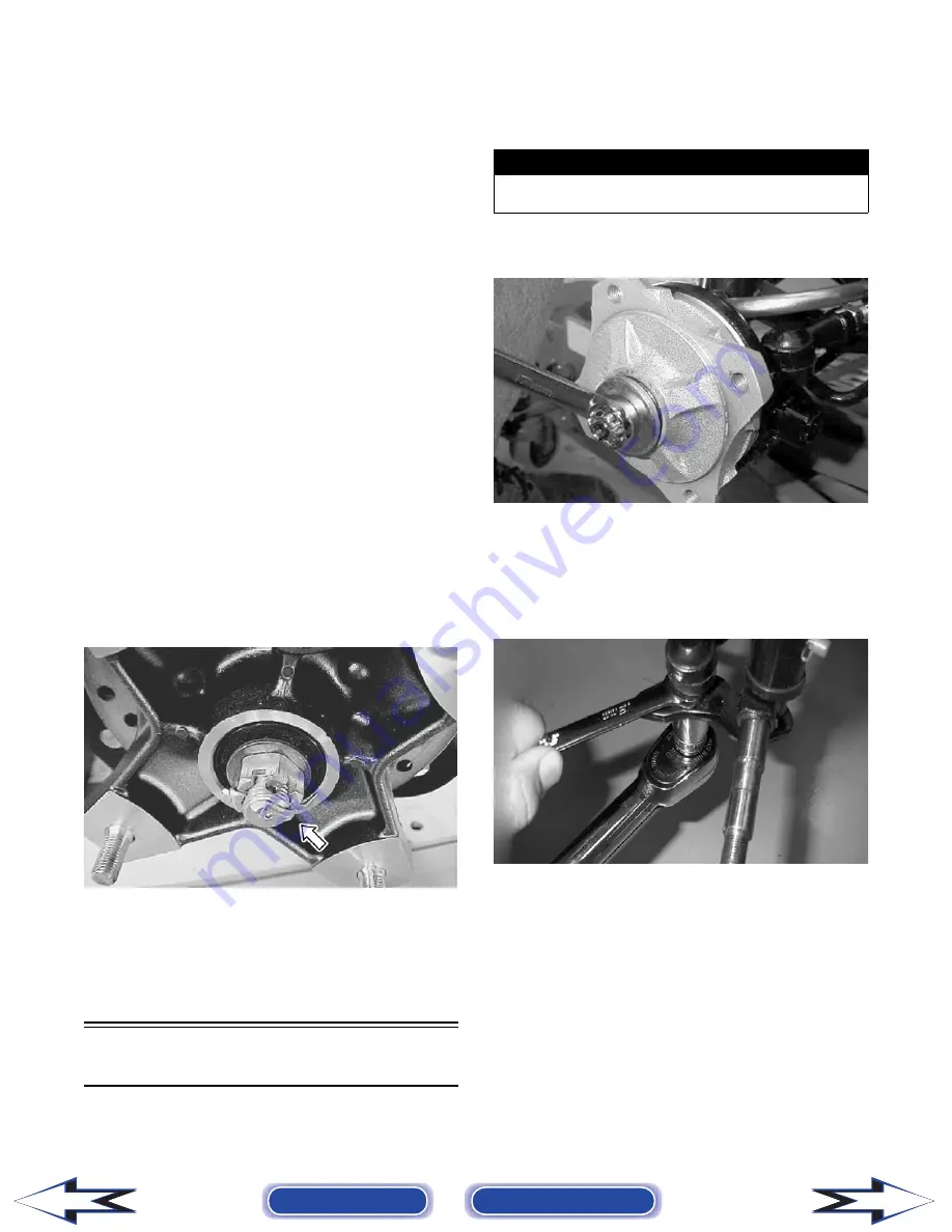
2. Remove the cotter pin, castle nut, and washer; then
remove the hub assembly.
MD2133
3. Slide brake backing plate assembly off the spindle
shaft and secure it out of the way.
4. Remove the cotter pin from the outer tie rod end;
then while holding the flat on the tie rod end,
remove the castle nut.
MD2428
5. Remove the tie rod end from the steering knuckle.
6. Remove the rubber spindle pin boot; then remove
the cotter pin and flanged castle nut from the spin-
dle pin. Lower the steering knuckle assembly from
the A-arm.
! WARNING
Make sure the ATV is solidly supported on the support
stand to avoid injury.
Back to TOC
Back to Section TOC
Next
Back
FOR ARCTIC CAT ATV DISCOUNT PARTS CALL 606-678-9623 OR 606-561-4983
www.mymowerparts.com


