50
MD1017
MD1018
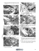
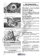
7. Install the clutch shoe assembly on the crankshaft;
then install the flange nut (left-hand thread) (coated
with red Loctite #271). Tighten to 147 ft-lb.
NOTE: The flat side of the flange nut should be
directed towards the clutch shoe.
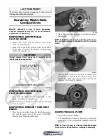
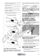
8. Install the one-way clutch making sure that the green
dot or the word OUTSIDE is directed away from the
crankcase.
MD1286
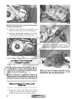
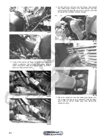
9. Install gear position switch spacer and switch mak-
ing sure to align the drive pin with the slot in the shift
shaft.
KC325A
KC326B
B. Clutch Cover
C. Fixed Drive Face
D. Movable Drive Face
NOTE: Steps 1-9 in the preceding sub-section must
precede this procedure.
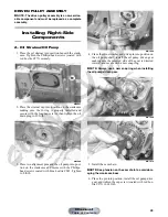
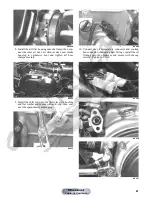
10. Install two alignment pins and place the clutch cover
gasket into position. Install the clutch cover.
MD1115
11. Tighten the clutch cover cap screws to 8 ft-lb.
CAUTION
Care must be taken when installing the flange nut; it has
“left-hand” threads.
Manual
Table of Contents


