87
AG925
3. While holding the actuator firmly forward, tighten
the front cap screw to hold the actuator in place; then
install but do not tighten the two remaining cap
screws.
KC295A
4. Loosen the front cap screw; then tighten the cap
screw on the driveshaft side.
AG926
NOTE: It is important to tighten this cap screw while
the others are loose to ensure proper seating of the
actuator.
5. Tighten the remaining cap screws; then connect the
electrical plug to the main harness.
6. Turn the ignition switch to the ON position and
check the operation by shifting the selector switch
several times.
7. Secure the wiring harness to the frame with a nylon
cable tie.
Front Differential
REMOVING DIFFERENTIAL
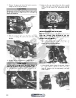
1. Secure the ATV on a support stand to elevate the
wheels.
2. Remove the drain plug and drain the gear lubricant
into a drain pan; then reinstall the plug and tighten to
45 in.-lb.
ATV0082A
3. Remove the front wheels.
4. Pump up the hand brake; then engage the brake lever
lock.
5. Remove the cotter pin securing the hex nut; then
remove the hex nut.
6. Release the brake lever lock.
NOTE: It is not necessary to remove the brake
hoses from the calipers for this procedure.
7. Remove the left and right brake calipers. Account for
the four cap screws.
KC187A
! WARNING
Make sure the ATV is solidly supported on the support
stand to avoid injury.
Manual
Table of Contents


