background image

3-81

3

GZ226

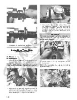
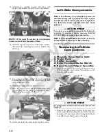
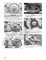
11. Place the key into the keyway in the crankshaft; then

wipe all oil from the crankshaft surface and rotor/fly-

wheel bore and install the rotor/flywheel onto the

crankshaft aligning the keyway with the key. Secure

with the nut (coated with red Loctite #271) tightened

to 105 ft-lb.

GZ225

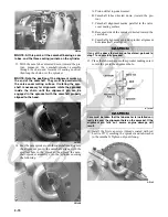
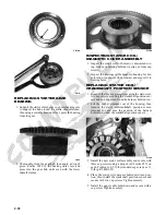
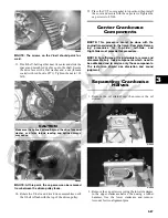
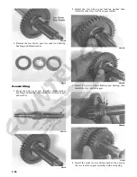
12. Install the starter driven and counter gear shafts (D)

into the crankcase (longer shaft to the front); then

install the starter countershaft gear (C), starter driven

gear (A), and bushing (B) making sure the cham-

fered gear teeth on the countershaft gear are directed

outward.

GZ224A

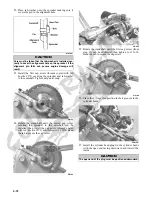
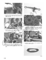
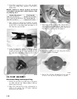
13. Install the starter motor with a new O-ring lightly

lubricated with grease; then tighten the mounting cap

screws to 8 ft-lb.

GZ251

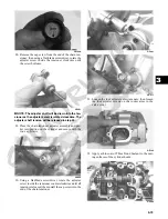
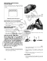
14. Using Seal Protector Tool, install the outer magneto

cover using a new gasket and secure with the cap

screws. Using the pattern shown, tighten to 8 ft-lb.

GZ212B

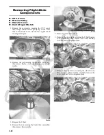
Right-Side Components

NOTE: For efficiency, it is preferable to remove and

disassemble only those components which need to
be addressed and to service only those components.
The technician should use discretion and sound
judgment.

NOTE: The engine/transmission does not have to

be removed from the frame for this procedure.

CAUTION

Make sure the one-way starter clutch is properly
engaged with the starter ring gear before installing and
tightening the rotor/flywheel nut or damage to the
clutch assembly could occur.



AT THIS POINT

To service any one specific component, only limited dis-
assembly of components may be necessary. Note the
AT THIS POINT information in each sub-section.

Summary of Contents for 2013 Prowler XT

Page 1: ...Prowler XT XTX XTZ ...

Page 2: ...ution Note and At This Point to emphasize important information The symbol WARNING identifies personal safety related information Be sure to fol low the directive because it deals with the possibility of serious personal injury or even death A CAUTION identi fies unsafe practices which may result in vehicle related damage Follow the directive because it deals with the possibility of damaging part ...

Page 3: ......

Page 4: ...NTENTS 1 General Information Specifications 2 Periodic Maintenance Tune Up 3 Engine Transmission 4 Fuel Lubrication Cooling 5 Electrical System 6 Drive System 7 Suspension 8 Steering Frame Controls 1 2 3 4 5 6 7 8 ...

Page 5: ......

Page 6: ...ION TABLE OF CONTENTS General Specifications 1 2 Torque Specifications 1 3 Torque Conversions ft lb N m 1 4 Break In Procedure 1 4 Gasoline Oil Lubricant 1 5 Genuine Parts 1 5 Preparation For Storage 1 6 Preparation After Storage 1 6 ...

Page 7: ...reen AC Generator Output no load 75 AC volts 5000 RPM black to black Ignition Timing 10 BTDC 1500 RPM VALVES AND GUIDES Valve Face Diameter intake exhaust 31 6 mm 27 9 mm Valve Tappet Clearance intake cold engine max exhaust 0 1016 mm 0 1524 mm Valve Guide Stem Clearance max 0 013 mm Valve Guide Valve Stem Deflection max wobble method 0 35 mm Valve Guide Inside Diameter 5 000 5 012 mm Valve Stem O...

Page 8: ...1 STEERING COMPONENTS Part Part Bolted To Torque ft lb N m Steering Wheel Steering Wheel Shaft 25 34 Steering Wheel Shaft Intermediate Shaft Upper 36 49 Intermediate Shaft Lower XT Steering Pinion Shaft 36 49 Rack and Pinion Assembly XT Frame 50 68 Rack and Pinion Assembly XTX XTZ Frame 35 48 Tie Rod XT Rack 52 70 Tie Rod XTX XTZ Rack 37 50 Tie Rod End Knuckle 30 41 Jam Nut Tie Rod End 10 14 EPS A...

Page 9: ...kcase 8 11 Speed Sensor Housing Crankcase 8 11 Shift Cam Stopper Crankcase 8 11 Shift Cam Stopper Spring Shift Cam Stopper 8 11 Shift Cam Plate Shift Cam Shaft 8 11 Shifter Housing Crankcase 8 11 Starter Motor Crankcase 8 11 V Belt Cover Crankcase 8 11 Oil Pump Cover Crankcase 8 11 Oil Strainer Cap Crankcase 8 11 Stator Coil Magneto Cover 8 5 11 5 Intake Boot Clamp Intake Boot 30 in lb 3 4 Starter...

Page 10: ...s SAE approved 80W 90 hypoid This lubricant meets all of the lubrication requirements of the Arctic Cat vehicle front differential and rear drive FILLING GAS TANK ATV0049B Since gasoline expands as its temperature rises the gas tank must be filled to its specified capacity only Expan sion room must be maintained in the tank particularly if the tank is filled with cold gasoline and then moved to a ...

Page 11: ...fter Storage Taking the vehicle out of storage and correctly preparing it will assure many miles and hours of trouble free riding 1 Clean the vehicle thoroughly 2 Clean the engine Remove the cloth from the exhaust system 3 Check all control wires and cables for signs of wear or fraying Replace if necessary 4 Change the engine transmission oil and filter 5 Check the coolant level and add properly m...

Page 12: ... 2 5 Spark Plug s 2 5 Muffler Spark Arrester 2 6 Engine Transmission Oil Filter 2 6 Front Differential Rear Drive Lubricant 2 7 Driveshaft Coupling 2 8 Nuts Bolts Cap Screws 2 8 Headlight Taillight Brakelight 2 8 Shift Lever XT XTZ 2 9 Shift Lever Shift Cable XTX 9 Hydraulic Brake System 2 10 Parking Brake XT XTZ 2 11 Burnishing Brake Pads 2 14 Checking Replacing V Belt 2 14 Troubleshooting Brake ...

Page 13: ...e I I A Engine Compression I Spark Plug s I I I R 4000 Mi or 18 Mo Muffler Spark Arrester C R Gas Hoses I I R 2 Yrs Throttle Cable Ends Accelerator Pedal Pivot I I C L A R Engine Transmission Oil Level I A Engine Transmission Oil Filter R R R R R Front Differential Rear Drive Lubricant I I R 4 Yrs Tires Air Pressure I I R Steering Components I I I R V Belt I l R Suspension Ball joint boots drive a...

Page 14: ...nd remove the cover 3 Remove the air filter frame A then remove the foam filter element B PR576A 4 Fill a wash pan larger than the filter with a non flam mable cleaning solvent then dip the filter in the sol vent and wash it NOTE Foam Filter Cleaner and Foam Filter Oil are available from Arctic Cat 5 Dry the filter 6 Put the filter in a plastic bag then pour in air filter oil and work the filter R...

Page 15: ...ible GZ059 Valve Adjuster Procedure A Place the Valve Clearance Adjuster onto the jam nut securing the tappet adjuster screw then rotate the valve adjuster dial clockwise until the end is seated in the tappet adjuster screw B While holding the valve adjuster dial in place use the valve adjuster handle and loosen the jam nut then rotate the tappet adjuster screw clockwise until friction is felt C A...

Page 16: ... 4 Attach the Compression Tester Kit 5 While holding the throttle in the full open position crank the engine over with the electric starter until the gauge stops climbing five to 10 compression strokes 6 If compression is abnormally low verify the following items A Starter cranks engine over B Gauge is functioning properly C Throttle in the full open position D Valve tappet clearance correct E Eng...

Page 17: ...creen taking care not to damage the screen NOTE If the screen or gasket is damaged in any way it must be replaced 3 Install the spark arrester assembly and gasket and secure with the cap screws Tighten the cap screws to 48 in lb Engine Transmission Oil Filter OIL FILTER Change the engine oil and oil filter at the scheduled inter vals The engine should always be warm when the oil is changed so the ...

Page 18: ...in plug and oil filter for leaks Front Differential Rear Drive Lubricant To check lubricant use the following procedure 1 Remove the fill plug the lubricant level should be one inch below the plug threads PR530A 2 If low add SAE approved 80W 90 hypoid gear lube as necessary To change the lubricant use the following procedure 1 Place the vehicle on level ground 2 Remove each fill plug 3 Drain the l...

Page 19: ... the two machine screws and remove the light assembly 2 Rotate the bulb socket counterclockwise to remove it from the light assembly then pull straight out on the bulb Push the new bulb straight into the socket 3 Install the bulb and socket into the light assembly and turn clockwise to lock in place 4 Install the taillight brakelight assembly on the can opy support CHECKING ADJUSTING HEADLIGHT AIM...

Page 20: ...ver is in neutral then remove the E clip securing the cable end to the shaft arm PR567A 3 Loosen nuts A and B and adjust the cable housing to align the shift cable end to the shift arm stud C PR568A PR572A 4 Install the E clip then tighten the nuts A and B securely 5 Check each gear shift position for proper gear selec tion and make sure the proper icon illuminates on the LCD then install the cent...

Page 21: ...ECKING BLEEDING The hydraulic brake system has been filled and bled at the factory To check and or bleed a hydraulic brake sys tem use the following procedure 1 With the master cylinder in a level position check the fluid level in the reservoir If the level in the res ervoir is not above the MIN add DOT 4 brake fluid PR095 2 Depress the brake pedal several times to check for a firm brake If the br...

Page 22: ...rake pad is less than 1 0 mm 0 039 in the brake pads must be replaced NOTE The brake pads should be replaced as a set 4 To replace the brake pads use the following proce dure A Remove the wheel B Remove the cap screws securing the caliper holder to the knuckle then remove the pads from the caliper PR237 C Install the new brake pads D Secure the caliper holder to the knuckle with new patch lock cap...

Page 23: ...ake Pads in this sub section MEASURING REPLACING BRAKE PADS XT Removing 1 Remove the parking brake cable see Adjusting in this sub section 2 Lift the cargo box then disconnect the lower lift sup port and allow the cargo box to tilt all the way back Account for the washer PR473A 3 Remove the two cap screws securing the brake cali per to the rear drive housing and remove the caliper 4 Remove the ant...

Page 24: ... replaced as a set 1 Disconnect the parking brake cable from the actuator arm Account for a flat washer PR681A 2 Remove the two cap screws and nuts securing the cable support to the brake caliper PR677A 3 Remove the two cap screws securing the brake cali per to the gear case housing then remove the caliper assembly from the vehicle PR683A 4 Remove the two lock nuts A from the brake pad anchor bolt...

Page 25: ...te to 0 5 mph 3 Repeat procedure 20 times until brake pads are bur nished 4 Adjust the parking brake if necessary 5 Verify that the park indicator light illuminates when the parking brake is set ignition switch on Checking Replacing V Belt REMOVING 1 Remove the seats and center console then remove the left side seat base XT XTX or right side seat base XTZ 2 Remove the cap screws securing the V bel...

Page 26: ...b GZ485A NOTE At this point remove the cap screw from the driven pulley face 3 Rotate the V belt and driven pulley clutch until the V belt is flush with the top of the driven pulley 4 Place the V belt cover gasket into position then install the cover and secure with the cap screws mak ing sure the different lengthed cap screws are in their proper location Tighten the cap screws to 8 ft lb 5 Secure...

Page 27: ...essive Condition Remedy 1 Brake fluid low 2 Piston seal cup worn 1 Add fluid to proper level 2 Replace seal cup Problem Brake fluid leaking Condition Remedy 1 Fittings loose 2 Hose cracked 3 Piston seal worn 1 Tighten fittings 2 Replace hose 3 Replace seal Problem Brake pedal spongy Condition Remedy 1 Air trapped in hydraulic system 2 Brake fluid low 1 Bleed hydraulic system 2 Add brake fluid and ...

Page 28: ...3 1 3 SECTION 3 ENGINE TRANSMISSION TABLE OF CONTENTS Engine Transmission 3 2 Troubleshooting 3 3 Prowler XT XTX Table of Contents 3 5 Prowler XTZ Table of Contents 3 51 ...

Page 29: ...TE Some photographs and illustrations used in this section are used for clarity purposes only and are not designed to depict actual conditions NOTE Critical torque specifications are located in Section 1 SPECIAL TOOLS A number of special tools must be available to the techni cian when performing service procedures in this section Refer to the current Special Tools Catalog for the appro priate tool...

Page 30: ... Replace ECM 4 Replace fuel injector 5 Adjust clearance Problem Engine noisy Excessive valve chatter Condition Remedy 1 Valve clearance excessive 2 Valve spring s weak broken 3 Rocker arm rocker arm shaft worn 4 Camshaft worn 1 Adjust clearance 2 Replace spring s 3 Replace arm shaft 4 Replace camshaft Problem Engine noisy Noise seems to come from piston Condition Remedy 1 Piston cylinder worn 2 Co...

Page 31: ...erfilled contaminated 2 Piston rings cylinder worn 3 Valve guides worn 4 Cylinder wall scored 5 Valve stems worn 6 Stem seals defective 1 Drain excess oil change oil 2 Replace service rings cylinder 3 Replace guides 4 Replace cylinder 5 Replace valves 6 Replace seals Problem Engine lacks power Condition Remedy 1 Valve clearance incorrect 2 Valve springs weak 3 Valve timing incorrect 4 Piston ring ...

Page 32: ...t information Support the vehicle on a suitable lift or jack stands allow ing room to perform work from the underside NOTE Locate the jack stands to allow removing of the center belly panel 1 Remove the seats and center console then remove the left side and right side seat bases 2 Remove the center belly panel then drain the oil and coolant NOTE Use a small funnel between the frame and coolant dra...

Page 33: ...crew securing the main harness ground and the battery ground wires to the starter PR145A PR266C PR474B 6 Remove the E clip from the transmission shift arm then disconnect the cable Remove the gear position switch connector XTZ PR567A PR825A 7 Remove four machine screws securing the shifter mount to the frame then remove the shifter assembly PR596A ...

Page 34: ... frame then remove the air filter and mounting bracket as an assembly PR140A 10 Remove the throttle arm cover from the throttle body then disconnect and remove the throttle cable and the throttle body PR154A 11 Remove the coolant hoses from the water pump and thermostat housings then position the upper coolant line to the left side of the engine compartment PR150A 12 Remove the exhaust duct from t...

Page 35: ...ting bracket should slide free of the engine mounts first then the rear engine mounting bracket and two rear engine mounts will lift free of the frame PR146 Top Side Components NOTE For efficiency it is preferable to remove and disassemble only those components which need to be addressed and to service only those components The technician should use discretion and sound judgment NOTE The engine tr...

Page 36: ...ote the location of two alignment pins CD205 CD206 CD211A 3 Loosen the cap screw on the end of the tensioner then remove the two cap screws securing the ten sioner adjuster assembly and remove the assembly Account for a gasket CC009D 4 Using an awl rotate the C ring in its groove until it is out of the cylinder head then remove the C ring NOTE Care should be taken not to drop the C ring down into ...

Page 37: ...n remove the tensioner FI617 8 Remove the five nuts securing the cylinder head to the cylinder then remove the four cylinder head cap screws CC017D CC018D 9 Remove the cylinder head from the cylinder remove the gasket and account for two alignment pins then remove the cam chain guide CC020D AT THIS POINT To service valves and cylinder head see Servicing Top Side Components sub section AT THIS POIN...

Page 38: ...o drop against the crankcase Account for the gasket and two alignment pins CC024D CC025D CC026D 13 Using an awl remove one piston pin circlip CC032D 14 Using the Piston Pin Puller remove the piston pin Account for the opposite side circlip Remove the piston NOTE It is advisable to remove the opposite side circlip prior to using the puller AT THIS POINT To service cylinder see Servicing Top Side Co...

Page 39: ... the valve cover in a figure eight motion until a uniform bright metallic finish is attained CC130D Removing Valves NOTE Keep all valves and valve components as a set Note the original location of each valve set for use during installation Return each valve set to its original location during installation 1 Using a valve spring compressor compress the valve springs and remove the valve cotters Acc...

Page 40: ...re the width of the valve face ATV 1004 2 Acceptable width ranges must be within specifica tions Measuring Valve Face Radial Runout 1 Mount a dial indicator on the surface plate then place the valve stem on a set of V blocks 2 Position the dial indicator contact point on the out side edge of the valve face then zero the indicator ATV1082A 3 Rotate the valve in the V blocks 4 Maximum runout must no...

Page 41: ...ecifi cations Measuring Rocker Arm Shaft Outside Diameter 1 Using a micrometer measure the outside diameter of the rocker arm shaft 2 Acceptable outside diameter must be at or above specifications Installing Valves 1 Apply grease to the inside surface of the valve seals then place a lower spring seat and valve guide seal over each valve guide CC144D 2 Insert each valve into its original location 3...

Page 42: ...meter of each piston for signs of excessive blowby Excessive blowby indicates worn piston rings or an out of round cylinder Measuring Piston Ring End Gap Installed 1 Place each compression ring in the wear portion of the cylinder Use the piston to position each ring squarely in the cylinder 2 Using a feeler gauge measure each piston ring end gap Acceptable ring end gap must not exceed speci ficati...

Page 43: ...cannot be trued they must be replaced as an assembly Cleaning Inspecting Cylinder Head 1 Using a non metallic carbon removal tool remove any carbon buildup from the combustion chamber being careful not to nick scrape or damage the com bustion chamber or the sealing surface 2 Inspect the spark plug hole for any damaged threads Repair damaged threads using a heli coil insert 3 Place the cylinder hea...

Page 44: ...chips 2 If the chain guide is damaged it must be replaced Honing Cylinder 1 Using a slide gauge and a dial indicator or a snap gauge measure the cylinder bore diameter in three locations from top to bottom and again from top to bottom at 90 from the first measurements for a total of six measurements The trueness out of round ness is the difference between the highest and low est reading Maximum tr...

Page 45: ...cessive scoring seizure marks or pitting is found the cylinder head assembly must be replaced Measuring Camshaft to Cylinder Head Clearance 1 Remove the adjuster screws and jam nuts CC005D 2 Place a strip of plasti gauge in each of the camshaft lands in the cylinder head 3 Place the valve cover on the cylinder head and secure with the valve cover cap screws Tighten securely NOTE Do not rotate the ...

Page 46: ...talled so the arrow points toward the exhaust CC032D 2 Place the two alignment pins into position Place the cylinder gasket into position then place a piston holder or suitable substitute beneath the piston skirt and square the piston in respect to the crankcase CF083 3 Lubricate the inside wall of the cylinder then using a ring compressor compress the rings and slide the cylinder over the piston ...

Page 47: ...020D CF289A 8 Install the four cylinder head cap screws Tighten only until snug CC272D 9 Loosely install the five cylinder head nuts 10 In a crisscross pattern tighten the four cylinder head cap screws from step 8 in 10 ft lb increments to 40 ft lb then tighten the 8 mm nut from step 9 to 18 ft lb Using a crisscross pattern tighten the 6 mm nuts from step 9 to 8 ft lb Tighten the two cylin der to ...

Page 48: ...463 15 Seat the cam sprocket onto the camshaft making sure the alignment pin in the camshaft aligns with the smallest hole in the sprocket then place the cam shaft sprocket assembly onto the cylinder ensuring the following CF013A A Piston still at top dead center B Camshaft lobes directed down toward the pis ton C Camshaft alignment marks parallel to the valve cover mating surface D Recessed side ...

Page 49: ...nder head CC012D 21 Install the cylinder head plug in the cylinder head with the open end facing downward and toward the inside GZ162A 22 Remove the cap screw from the end of the chain ten sioner then using a flat blade screwdriver rotate the adjuster screw inside the tensioner clockwise until the screw bottoms CD501 NOTE The adjuster shaft will be drawn into the ten sioner as the adjuster screw i...

Page 50: ...s of the cylinder head and valve cover CC275D 27 Place the valve cover into position NOTE At this point the rocker arms and adjuster screws must not have pressure on them 28 Install the four top side cap screws with rubber wash ers then install the remaining cap screws Tighten only until snug CC003D 29 In a crisscross pattern starting from the center and working outward tighten the cap screws from...

Page 51: ...he crankshaft then remove the spacer Account for the O ring PR465 3 Using a cold chisel scribe a mark showing the rela tive position of the shift arm to the shift arm shaft to aid in installing then remove the shift arm PR429A 4 Remove the cap screws securing the speed sensor housing to the crankcase and remove the housing assembly then remove the snap ring securing the speed sensor trigger to the...

Page 52: ...e inside of the right side cover for any shaft washers that may have come off with the cover Make sure they are returned to their respective shafts and the starter idler gear spacer is on the shaft or in the cover CF075A 9 Remove the nut securing the magneto rotor to the crankshaft then install the magneto rotor puller adapter NOTE The puller has left hand threads 10 Using Magneto Rotor Remover Se...

Page 53: ...assembling purposes Account for two washers PR430A 15 Remove the gear shift cam plate then remove the shift cam stopper and cam stopper spring Account for two washers PR434A Servicing Right Side Components INSPECTING STARTER CLUTCH GEAR 1 Place the starter clutch gear onto the rotor fly wheel and attempt to rotate the starter clutch gear clockwise It should lock up to the rotor flywheel Rotate the...

Page 54: ...lled with the notches directed away from the rotor fly wheel FI576A FI578 REPLACING STARTER GEAR BEARING 1 Support the starter clutch gear in a press making sure to support the hub around the entire circumference then using a suitable bearing driver press the bearing from the gear FI583 2 Thoroughly clean the gear hub then apply a drop of green Loctite 620 to the bearing outer race and press into ...

Page 55: ...rd cap screw or 11 ft lb p n 8409 632 4 Place the stator wire harness hold down into posi tion then install the crankshaft position sensor and secure with two cap screws Tighten securely 5 Install the upper cable hold down and secure with a cap screw Tighten securely FI595A Installing Right Side Components NOTE Plug the oil passage in the crankcase hous ing prior to installing the drive gear drive...

Page 56: ...o starter gears with the beveled side of the intermedi ate gear facing inward as noted in removing CD139 PR447A 4 In order on the crankshaft install a washer ring gear key and the magneto rotor Secure with the nut threads coated with red Loctite 271 Tighten to 105 ft lb CD948A CD940B 5 Install the shift cam plate onto the shift cam shaft then coat the cap screw threads with red Loctite 271 and tig...

Page 57: ...n the two alignment pins Make sure the outer shift shaft washer is in place PR431A 9 Install the magneto cover and secure with the cap screws Tighten only until snug 10 Place the spacer into position on the crankshaft mak ing sure a new lubricated O ring is inside the spacer Tighten the flange nut to 28 ft lb PR465 11 Tighten the cap screws from step 9 to 8 ft lb 12 Clean the countershaft and trig...

Page 58: ...ose components which need to be addressed and to service only those components The technician should use discretion and sound judgment NOTE The engine transmission does not have to be removed from the frame for this procedure Removing Left Side Components A V Belt Cover B Driven Pulley C Clutch Cover 1 Remove the cap screws securing the V belt cover noting the location of the different lengthed ca...

Page 59: ...B NOTE To aid in installing it is recommended the assemblies are kept together and IN ORDER PR398B 7 Remove the one way clutch D from the clutch housing Note the location of the green dot or the word OUTSIDE for installing purposes 8 Using a hydraulic press remove the clutch housing assembly from the clutch cover Account for the left fixed drive spacer and an O ring inside the fixed drive spacer C...

Page 60: ...the gear position switch then remove the sensor Account for two neutral contact pins and two springs XT only CD997 10 Remove the nut left hand threads securing the clutch shoe assembly C FI279A 11 Remove the cap screw securing the oil pump drive gear B Account for a cap screw washer pin and spacer CC606 CD987 CD993 XT ...

Page 61: ...r a part is worn excessively cracked damaged in any way or out of tolerance replacement is necessary INSPECTING CENTRIFUGAL CLUTCH SHOE Inspect the clutch shoes for wear or damage If any shoe is worn to the bottom of the groove replace the clutch assembly ATV1014 INSPECTING CLUTCH HOUSING 1 Inspect the clutch housing for burns grooving cracks or uneven wear 2 If the housing is damaged in any way t...

Page 62: ...ntact pins and the two springs XT only are properly positioned Tighten the cap screws securely CD997 CD994 2 Install the secondary shaft bearing housing making sure the two alignment pins are properly positioned Tighten the cap screws to 28 ft lb CD999 3 Install the oil pump onto the engine then tighten the cap screws securely CD988 4 Install the oil pump drive gear spacer onto the crank balancer ...

Page 63: ...nstall the clutch shoe assembly and secure with the flange nut threads coated with red Loctite 271 Tighten to 221 ft lb PR410A 7 Install the clutch cover alignment pins into the crank case apply oil to the cover gasket and install the gasket onto the crankcase 8 Install the one way clutch onto the clutch shoe assembly PR399A 9 Lightly grease the clutch housing seal then insert the left fixed drive...

Page 64: ...71 securely CD971 CD970 13 Place the driven pulley assembly into position and secure with the nut Using Spanner Wrench tighten to 80 ft lb 14 Slide the fixed drive face onto the shaft 15 Spread the faces of the driven pulley by threading a 6 mm cap screw into the threaded boss then turn clockwise until pulley faces are opened approxi mately 1 2 in 16 Place the V belt into position on the driven pu...

Page 65: ...scretion and sound judgment Separating Crankcase Halves 1 Remove the left side cap screws securing the crank case halves Note the location of the differ ent lengthed cap screws 2 Remove the right side cap screws securing the crankcase halves Note the location of the differ ent lengthed cap screws 3 Using the Crankcase Separator Crankshaft Remover and tapping lightly with a rubber mallet separate t...

Page 66: ... the two holes on the end of the shaft Account for a spacer and a washer DE677A 5 Remove the countershaft assembly D Account for a washer on each end of the countershaft CC674 NOTE Do not disassemble the countershaft assem bly unless necessary If necessary see Servicing Center Crankcase Components sub section 6 Using a rubber mallet tap on the crankcase to remove the driveshaft E CC675 7 Note the ...

Page 67: ...p NOTE If the secondary output driven shaft is replaced or disassembled the initial set up must be performed to establish correct gear tooth contact If only the secondary output drive shaft or secondary output driven gear is replaced proceed to Correcting Backlash in this sub section 1 Install a new bearing A onto the secondary driven shaft B making sure the bearing locating groove is directed awa...

Page 68: ...cking Backlash 1 If removed install the secondary drive bevel gear shaft into the crankcase then tighten the nut to 59 ft lb 2 Install the secondary drive bearing support then install the secondary driven output shaft into the crankcase 3 Mount the dial indicator so the tip is contacting a tooth on the secondary drive bevel gear 4 While rocking the drive bevel gear back and forth note the maximum ...

Page 69: ...nd journal 2 Zero the indicator and push the small end of the con necting rod away from the dial indicator 3 Maximum deflection must not exceed specifications Measuring Connecting Rod Big End Side to Side 1 Push the lower end of the connecting rod to one side of the crankshaft journal 2 Using a feeler gauge measure the gap between the connecting rod and crankshaft journal CC289D 3 Acceptable gap r...

Page 70: ...he snap ring securing the reverse driven gear dog and bushing to the countershaft GZ296 GZ312 3 Remove the reverse driven gear dog GZ313A 4 Remove the snap ring securing the reverse driven gear and washer then remove the washer and gear GZ314 CAUTION When disassembling the countershaft care must be taken to note the direction each major component dog gear faces If a major component is installed fa...

Page 71: ...e low driven gear Account for a bearing bushing and thrust washer GZ316 Assembling 1 From the drive gear end install a thrust washer bushing and bearing then install the low driven gear and washer GZ317A GZ318 2 Install the low driven gear locking washer then install the inner reverse driven gear washer GZ319B GZ320B ...

Page 72: ...shaft and secure with a snap ring GZ313A GZ312 6 From the opposite end of the countershaft install the high low driven gear dog A thrust washer B bushing C bearing D high low driven gear E and spacer washer F GZ283B 7 Install the drive gear washer and the shift forks The countershaft is now ready for installation NOTE When installing the countershaft assembly account for the washer on each end of ...

Page 73: ...nk balancer CD832B NOTE It will be necessary to rotate the crank bal ancer until the counterweight is facing away from the crankshaft then rotate the crankshaft clockwise into the journal area to allow the crank balancer to be fully seated 4 Place the key into the crank balancer keyway then install the crank balancer gear making sure the align ment dots on the crank balancer gear and the crank sha...

Page 74: ... fully seated in the crankcase CD268A 11 Place the oil strainer into position then secure with the two screws 12 Place the oil strainer cap into position making sure the O ring is in position then secure the cap with cap screws Tighten securely Joining Crankcase Halves 1 Apply High Temp Sealant to the right side mating surface smoothing out any build up or bumps 2 Lightly oil all bearings and grea...

Page 75: ...be in the frame 2 Align the rear engine mount studs with the holes in the frame and slowly lower into place The front engine mounting bracket will then slip over the engine mount studs PR146 3 Install the flange nuts on the rear engine mount studs then secure the front engine mounting bracket to the front engine mount studs with two flange nuts Tighten the four flange nuts to 45 ft lb PR153A PR147...

Page 76: ... hose to the water pump housing then connect the upper coolant hose to the thermostat housing Tighten the hose clamps securely 8 Install the starter wire on the starter and tighten the nut securely then connect the alternator connector and gear position switch connector XT PR838 PR266C 9 From the right side connect the speed sensor con nector fuel level sensor connector and temperature sensor lead...

Page 77: ...E Before operating vehicle check and adjust shift cable as required see Section 2 14 Fill the engine transmission with the appropriate lubricant 15 Remove the coolant bleed screw from the upper coolant pipe near the thermostat then pour the cor rect mixture of coolant into the radiator When cool ant with no air bubbles flows from the bleed hole install the screw and tighten securely then complete ...

Page 78: ...rmation Support the vehicle on a suitable lift or jack stands allow ing room to perform work from the underside NOTE Locate the jack stands to allow removing of the center belly panel 1 Remove the seats and center console then remove the left side and right side seat bases 2 Remove the storage console then remove the floor and drain the oil into a suitable container PR611 3 Clamp off the lower rad...

Page 79: ...nector E PR594A 8 Remove the rear spark plug cap then from the left side remove the fuel injector connector A mani fold absolute pressure MAP sensor B parking brake warning switch C reverse override switch connector D and idle speed control ISC valve E PR595A 9 Disconnect the front ignition coil and remove the front spark plug then route the engine harness out of the engine compartment PR596 10 Fr...

Page 80: ... NOTE The parking brake cable does not need to be disconnected 14 Using a shop towel to absorb any spilled gasoline remove the quick disconnect fuel couplers from the fuel injectors PR663A 15 Remove four sheet metal screws securing the air fil ter mounting bracket to the frame then loosen the intake boot clamp and remove the air filter assembly CAUTION The gear position switch wires are secured to...

Page 81: ...ostat housing then move the coolant pipe to the left side of the vehicle PR607A 19 Remove the sheet metal screws securing the constant variable transmission CVT cooling duct to the frame then loosen the hose clamps and remove the duct from the front elbow and CVT boot PR671A 20 Remove the inlet boot from the CVT cover then remove the outlet boot from the rear of the CVT cover PR670A 21 Remove the ...

Page 82: ...haust pipe to the cylinder head then remove two springs securing the front and rear exhaust pipes together Remove the front exhaust pipe Account for a grafoil seal and a grafoil gasket PR643A PR661A PR625A NOTE The grafoil gasket may remain in the cylinder head 24 Remove the cap screws securing the rear exhaust pipe to the cylinder head and remove the exhaust pipe Account for a grafoil gasket ...

Page 83: ...output yoke PR638A PR639A 26 Remove four cap screws securing the rear driveshaft to the output flange The rear driveshaft can remain on the vehicle PR647 27 Remove the lock nuts from the engine through bolts then attach a lifting chain to the engine transmission PR630 PR629 PR631 28 Using a suitable engine hoist remove the weight from the through bolts then remove the bolts Account for a flat wash...

Page 84: ...omponents A Valve Cover Rocker Arms B Cylinder Head Camshaft 1 Remove the timing inspection plug spark plugs and magneto housing cover then install the 10 mm cap screw left hand threads in the crankshaft and rotate the desired cylinder to top dead center of the com pression stroke GZ027 GZ026 NOTE Timing marks on the rotor flywheel are stamped with an F front cylinder and R rear cyl inder adjacent...

Page 85: ... the tension Remove the two cap screws securing the tensioner adjuster assembly and remove the assembly Account for a gasket GZ200 5 Using an awl rotate the C ring in its groove until it is out of the cylinder head then remove the C ring NOTE Care should be taken not to drop the C ring into the crankcase GZ155 6 Bend the washer tabs down and remove the two cap screws securing the sprocket to the c...

Page 86: ...Remove the cylinder head from the cylinder remove the gasket and account for two alignment pins then remove the cam chain guide GZ151 GZ161 10 If the remaining cylinder head is to be serviced apply tension to the loose timing chain and rotate the second cylinder to top dead center of the compres sion stroke then repeat steps 2 9 on the other cylin der head AT THIS POINT To service valves and cylin...

Page 87: ...nt for the gasket and two alignment pins GZ142 GZ144 14 Using an awl remove one piston pin circlip GZ145 15 Using the Piston Pin Puller remove the piston pin Account for the opposite side circlip Remove the piston NOTE It is advisable to remove the opposite side circlip prior to using the puller NOTE Support the connecting rod with rubber bands or a piece of hose to avoid damaging the rod or insta...

Page 88: ...right metallic finish is attained CC130D Removing Valves NOTE Keep all valves and valve components as a set Note the original location of each valve set for use during installation Return each valve set to its original location during installation 1 Using a valve spring compressor compress the valve springs and remove the valve cotters Account for an upper spring retainer CC132D 2 Remove the valve...

Page 89: ...ace Seat Width 1 Using a micrometer measure the width of the valve face ATV 1004 2 Acceptable width range must be within specifica tions Measuring Valve Face Radial Runout 1 Mount a dial indicator on the surface plate then place the valve stem on a set of V blocks 2 Position the dial indicator contact point on the out side edge of the valve face then zero the indicator ATV1082A 3 Rotate the valve ...

Page 90: ...ptable outside diameter must be at or above specifications Installing Valves 1 Apply grease to the inside surface of the valve seals then place a lower spring seat and valve guide seal over each valve guide CC144D 2 Insert each valve into its original location 3 Install the valve springs with the painted end of the spring facing away from the cylinder head NOTE If the paint is not visible install ...

Page 91: ...sing a feeler gauge measure each piston ring end gap Acceptable ring end gap must be within specifi cations CC280D Measuring Piston Pin Outside Diameter and Piston Pin Bore 1 Measure the piston pin outside diameter at each end and in the center If measurement is not within speci fications the piston pin must be replaced ATV 1070 2 Insert an inside dial indicator into the piston pin bore The diamet...

Page 92: ...hole for any damaged threads Repair damaged threads using a heli coil insert 3 Place the cylinder head on the surface plate covered with 400 grit wet or dry sandpaper Using light pressure move the cylinder head in a figure eight motion Inspect the sealing surface for any indication of high spots A high spot can be noted by a bright metallic finish Correct any high spots before assem bly by continu...

Page 93: ... the first measurements for a total of six measurements The trueness out of round ness is the difference between the highest and low est reading Maximum trueness out of roundness must not exceed specifications CC127D 2 Wash the cylinder in parts cleaning solvent 3 Inspect the cylinder for pitting scoring scuffing and corrosion If marks are found repair the surface using a 320 grit ball hone NOTE T...

Page 94: ...of the camshaft lands in the cylinder head 3 Place the valve cover on the cylinder head and secure with the valve cover cap screws Tighten securely NOTE Do not rotate the camshaft when measuring clearance 4 Remove the cap screws securing the valve cover to the cylinder then remove the valve cover and cam shaft 5 Match the width of the plasti gauge with the chart found on the plasti gauge packaging...

Page 95: ... substitute beneath the piston skirt and square the piston in respect to the crankcase GZ159 3 Lubricate the inside wall of the cylinder then using a ring compressor compress the rings and slide the cylinder over the piston Route the cam chain up through the cylinder cam chain housing then remove the piston holder and seat the cylinder firmly on the crankcase GZ142 4 Loosely install the two nuts s...

Page 96: ...inder head nuts 10 In a crisscross pattern tighten the four cylinder head cap screws from step 8 to 38 ft lb then tighten the 8 mm nut from step 9 to 18 ft lb Using a crisscross pattern tighten the 6 mm nuts from step 9 to 8 ft lb Tighten the two cylinder to crankcase nuts from step 4 securely NOTE If both cylinders have been removed repeat steps 1 10 for the remaining cylinder 11 With the timing ...

Page 97: ...mallest hole in the sprocket then place the cam shaft sprocket assembly onto the cylinder ensuring the following GZ190B A Piston still at top dead center B Camshaft lobes directed down toward the pis ton C Camshaft alignment marks parallel to the valve cover mating surface D Recessed side of the sprocket directed toward the cam lobes E Camshaft alignment pin and sprocket alignment hole smallest ar...

Page 98: ...g surface If rotating the cam shaft is necessary for alignment rotate the sprocket inside the chain until the alignment pin can be engaged in the sprocket with the camshaft properly aligned to the head GZ190C GZ190B 21 Seat the cam sprocket onto the camshaft making sure the alignment pin in the camshaft aligns with the smallest hole in the sprocket then place the cam shaft sprocket assembly onto t...

Page 99: ...11 ft lb Bend the tab to secure the cap screw GZ193 CD465 25 Rotate the crankshaft until the first cap screw from step 23 can be addressed then tighten to 11 ft lb Bend the tab to secure the cap screw GZ194 26 Place the C rings into position in their grooves in the cylinder heads CC012D 27 Install the cylinder head plugs in the cylinder heads with the open end facing downward and toward the inside...

Page 100: ...0 29 Place the chain tensioner adjuster assembly and gas ket into position on the cylinder and secure with the two cap screws CD469 30 Using a flat blade screwdriver rotate the adjuster screw inside the tensioner counterclockwise until all tension is released then install the cap screw into the end of the chain tensioner GZ201 CD471 31 Loosen the four adjuster screw jam nuts then loosen the four a...

Page 101: ...nd disassemble only those components which need to be addressed and to service only those components The technician should use discretion and sound judgment NOTE The engine transmission does not have to be removed from the frame for this procedure Removing Left Side Components A Magneto Cover Stator Coils B Water Pump C Shifter Assembly D Rotor Flywheel Starter Clutch E Speed Sensor Trigger Assemb...

Page 102: ... 4 Install Magneto Rotor Remover Set and loosen the rotor flywheel then remove the crankshaft protector and rotor flywheel from the crankshaft Account for the flywheel key GZ216 GZ217 5 With the flywheel key removed remove the starter ring gear and spacer washer GZ226 GZ249 6 Remove the hose clamps from the water pump then remove the coolant hoses from the water pump out lets and coolant pipes GZ2...

Page 103: ...ve come off with the cover Make sure they are returned to their respective shafts GZ231A GZ233A 9 Remove the nut A from the shift cam stopper B then remove the cam stopper spring C Account for a flat washer D GZ236A 10 Remove the cap screw securing the shift cam plate to the shift cam shaft and remove the shift cam plate then remove the shift shaft Account for a washer GZ234B 11 Remove the cap scr...

Page 104: ...tion scoring of the clutch surface Inspect the bearing for loose worn or discolored rollers If bearing is damaged it must be replaced FI569 3 Inspect the one way bearing for chipped surfaces missing rollers or discoloration If any of the above conditions exist replace the starter clutch assembly FI572 REPLACING STARTER CLUTCH ASSEMBLY 1 Remove the cap screws securing the one way clutch assembly to...

Page 105: ...ted and secure fit in bearing bores REPLACING STATOR COIL CRANKSHAFT POSITION SENSOR 1 Remove the three cap screws securing the stator coil two cap screws securing the crankshaft position sen sor and one cap screw from the harness hold down 2 Lift the rubber grommet out of the housing then remove the stator coil crankshaft position sensor Account for and note the position of the harness hold down ...

Page 106: ...d trigger splines thoroughly and install the inner snap ring onto the shaft then apply green Loctite 620 to the trigger and counter shaft splines and install the trigger Secure with a flat washer and outer snap ring GZ253 GZ254 4 Using a new gasket install the speed sensor housing onto the crankcase and secure with two cap screws Tighten to 8 ft lb GZ232 5 If removed install the shift cam stopper ...

Page 107: ...all the shift shaft into the crankcase making sure the washers are properly located then align the tim ing reference marks and completely seat the shift shaft GZ258 GZ261 9 Apply grease to the lips of the shift shaft seal in the shifter housing then using a new gasket install the shifter housing and secure with the cap screws Tighten in a crisscross pattern to 8 ft lb GZ262 10 Install the spacer w...

Page 108: ...nting cap screws to 8 ft lb GZ251 14 Using Seal Protector Tool install the outer magneto cover using a new gasket and secure with the cap screws Using the pattern shown tighten to 8 ft lb GZ212B Right Side Components NOTE For efficiency it is preferable to remove and disassemble only those components which need to be addressed and to service only those components The technician should use discreti...

Page 109: ... movable drive face then remove the face Account for a spacer and a flat washer GZ074 CD966A 3 Remove the V belt 4 Remove the nut securing the fixed driven assembly then remove the assembly PR388 5 Remove the fixed drive face 6 Remove the cap screws securing the V belt housing to the crankcase then remove the V belt housing Account for two alignment pins GZ246A 7 Remove the cap screws securing the...

Page 110: ...utch cover Account for the left fixed drive spacer and an O ring inside the fixed drive spacer CF085 CC596 NOTE Account for and inspect the clutch housing seal 10 Remove the two cap screws securing the gear posi tion switch then remove the switch Account for two contact pins and two springs CD997 11 Remove the nut left hand threads securing the clutch shoe assembly GZ248A Servicing Right Side Comp...

Page 111: ...PUMP DRIVE ASSEMBLY NOTE Certain models have been built using an external water pump drive assembly When perform ing service procedures on the water pump the tech nician should use sound judgment in determining which type of pump is being serviced Disassembling 1 Remove the two snap rings from the driveshaft then remove the gear and drive pin noting the orientation of the gear for proper assembly ...

Page 112: ...rly positioned Tighten the cap screws securely CD997 GZ240 2 Install the clutch shoe assembly and secure with the flange nut threads coated with red Loctite 271 Tighten to 221 ft lb GZ241 3 Install the clutch cover alignment pins into the crank case apply oil to the cover gasket and install the gasket onto the crankcase 4 Apply grease to the outer edges of the clutch hous ing then from inside the ...

Page 113: ...d to 8 ft lb GZ263B GZ244A 9 Place the driven pulley assembly into position and secure with the nut coated with red Loctite 271 Tighten to 80 ft lb GZ066 10 Slide the fixed drive face onto the clutch shaft 11 Spread the faces of the driven pulley by threading in a cap screw then when the faces are separated insert the belt and push down between the faces GZ065A 12 Place the V belt into position on...

Page 114: ...o 8 ft lb Center Crankcase Components NOTE This procedure cannot be done with the engine transmission in the frame Complete Remov ing procedures for Top Side Left Side and Right Side must precede this procedure NOTE For efficiency it is preferable to remove and disassemble only those components which need to be addressed and to service only those components The technician should use discretion and...

Page 115: ...ght cap screws from the left side crankcase then using a rubber mallet separate the crankcase halves leaving all components in the right side case Account for a thrust washer on the crankshaft and flat washers on gear shift shaft countershaft and reverse idler Note the location of two alignment pins GZ454A GZ272B Disassembling Crankcase Half NOTE For steps 1 8 refer to illustration GZ474A GZ474A N...

Page 116: ...en remove the shaft and bearings GZ463A 4 Remove the snap ring securing the oil pump driven gear D to the oil pump driveshaft then remove the gear Account for a drive pin and washer GZ463B 5 Remove the shift fork shaft E then remove the gear shift shaft assembly F Account for a flat washer and a spacer DE677A GZ276 6 Remove two cap screws securing the oil pump in the crankcase and remove the oil p...

Page 117: ...ed or disassembled the initial set up must be performed to establish correct gear tooth contact If only the secondary output driveshaft or secondary output driven gear are replaced proceed to Correct ing Backlash in this sub section 1 Install a new bearing A onto the secondary driven shaft B making sure the bearing locating groove is directed away from the driven gear splines MT011A 2 Using a suit...

Page 118: ... Checking Backlash in this sub section Checking Backlash 1 Install the drive bevel gear assembly and driven bevel gear output shaft assembly into the crankcase bottom cover 2 Mount the dial indicator so the tip is contacting a tooth on the secondary drive bevel gear GZ396 3 Firmly hold the bearing down and while rocking the drive bevel gear back and forth note the maximum backlash reading on the g...

Page 119: ...sassembling and Inspecting 1 Remove the oil pump cover then remove the gerotor set shaft and pin see Disassembling Crankcase Half in this sub section 2 Inspect the crankcase for scoring discoloration or cracks in the gerotor bore If scored crankcase assembly must be replaced GZ357 3 Inspect the gerotor set for scoring discoloration or cracks then using a feeler gauge check the inner to outer rotor...

Page 120: ...r set separate the inner rotor from the outer rotor and with the ref erence dot directed toward the oil pump cover place the rotor on the shaft then install the drive pin and push the shaft into the rotor GZ356 GZ363 3 With the outer rotor reference dot directed toward the oil pump cover install the rotor onto the inner rotor GZ360 4 Place a new O ring seal on the outside of the oil pump cover The...

Page 121: ...ecting Rod Big End Side to Side 1 Push the lower end of the connecting rod to one side of the crankshaft journal 2 Using a feeler gauge measure the gap between the connecting rod and crankshaft journal 3 Acceptable gap range must be within specifications Measuring Crankshaft Runout 1 Place the crankshaft on a set of V blocks 2 Mount a dial indicator and base on the surface plate Position the indic...

Page 122: ...312 3 Remove the reverse driven gear dog GZ313A 4 Remove the snap ring securing the reverse driven gear and washer then remove the washer and gear GZ314 5 Remove the reverse driven washer then remove the low driven gear locking washer GZ320 GZ319 CAUTION When disassembling the countershaft care must be taken to note the direction each major component dog gear faces If a major component is installe...

Page 123: ...ring then install the low driven gear and washer GZ317A GZ318 2 Install the low driven gear locking washer then install the inner reverse driven gear washer GZ319B GZ320B 3 Install the reverse driven bushing and bearing then install the reverse driven gear GZ286A GZ287 4 Install the outer reverse driven washer then secure the reverse driven gear assembly with a snap ring ...

Page 124: ...r and the shift forks The countershaft is now ready for installation Assembling Crankcase Half 1 Install the oil pump gerotor assembly and oil pump cover in the crankcase and secure with two cap screws Coat the threads with red Loctite 271 and tighten securely to 8 ft lb GZ305 2 Install a flat washer drive pin and drive gear onto the oil pump shaft then secure with a snap ring flat side away from ...

Page 125: ...rankcase GZ474 NOTE It will be necessary to rotate the crankshaft back and forth to engage the teeth of the oil pump and countershaft gears 6 Install the driveshaft then with a flat washer on each end of the reverse idler assembly install into the crankcase GZ332 GZ333 7 Install the gear shift shaft into the crankcase making sure the flat washer is in place on the right case end and the spacer on ...

Page 126: ...port the connecting rods to align with the cylinder bores GZ340 2 Coat both sides with engine oil then install the spacer washer on the crankshaft with the radius directed toward the crankshaft GZ341 3 Install the two alignment pins then apply a thin bead of silicone sealant to the crankcase mating surface GZ345A 4 Carefully join the crankcase halves by placing the left side crankcase onto the ass...

Page 127: ...ear tooth contact and backlash 6 Install the locating ring in the crankcase assembly then install the secondary driven shaft assembly and secondary drive assembly making sure the locating ring and bearing engage correctly GZ269A GZ448A 7 Make sure the locating pins on the front and rear bearings are correctly seated in the crankcase 8 Install two alignment pins into the upper crankcase assembly th...

Page 128: ...ine transmission into the vehicle from the right side PR632A PR633 2 Carefully lower the engine transmission into position between the engine mounting tabs being careful to keep all cables wires and hoses clear then install the longer front through bolt with a flat washer PR634A 3 Install the rear through bolts with flat washer then secure both with new lock nuts and tighten to 40 ft lb PR629 AT T...

Page 129: ...tch mark on the front drive flange to mark on the front universal joint flange and secure with three cap screws Tighten to 40 ft lb and slide the rubber boot back into position PR638A PR640 7 Install a new grafoil gasket in the rear cylinder head then place the rear exhaust pipe into position and loosely secure with two cap screws PR641A 8 With a new grafoil gasket in the front cylinder head and a...

Page 130: ...ith two springs then tighten the cap screws from steps 7 and 8 to 20 ft lb PR661C PR668 10 Connect the oil cooler hoses to the engine and secure with the hose clamps Tighten securely PR616A PR617A 11 Install the inlet boot on the CVT cover then install the CVT cooling duct and secure with the sheet metal screw Tighten all fasteners and clamps securely PR615 PR671A ...

Page 131: ...l the air filter assembly and secure with four sheet metal screws then secure the intake boot to the throttle body Tighten the screws and clamp to 30 in lb PR603A 15 Connect the gasline hoses to the fuel rails making sure the quick disconnect couplers properly lock onto the fuel injector rails PR663 16 Install the shift support assembly and secure with four cap screws then secure the upper coolant...

Page 132: ...he left side connect the speed sensor connec tor F stator coil connector G CKP sensor H and gear position switch connector I PR658A 21 Route the engine harness through the shifter support brackets as marked during disassembly and secure with nylon cable ties PR591A 22 Connect the front spark plug cap and front ignition coil then install the front and rear injector connec tors A MAP sensor B parkin...

Page 133: ...ransmission 27 Remove the coolant bleed screw from the upper coolant pipe near the thermostat then pour the cor rect mixture of coolant into the radiator When cool ant with no air bubbles flows from the bleed hole install the screw and tighten securely PR662A 28 Start the engine and check for oil or coolant leaks then check all fluid levels and correct as necessary 29 Wipe off any spilled coolant ...

Page 134: ...XT XTX 4 2 Electronic Fuel Injection XTZ 4 3 Gas Tank 4 4 Gas Vent Hoses 4 7 Oil Filter Oil Pump 4 7 Oil Cooler XTZ 4 8 Liquid Cooling System 4 9 Radiator 4 9 Thermostat XT XTX 4 11 Thermostat XTZ 4 11 Fan 4 12 Water Pump XT XTX 4 12 Water Pump XTZ 4 13 Electric Fuel Pump Fuel Level Sensor 4 14 Troubleshooting 4 15 ...

Page 135: ... to crank the engine over at normal speed 5 Check the air filter housing and air filter for contam ination Clean or replace as necessary see Section 2 REMOVING THROTTLE BODY 1 Turn the ignition switch to the OFF position then remove the ignition switch key 2 Remove the left and right seats then remove the cen ter console and disconnect the battery 3 Remove the connector from the IAT sensor A then ...

Page 136: ...he ON position If no sound can be heard see Electric Fuel Pump Fuel Level Sensor in this section 2 Check for a flashing EFI icon on the LCD If EFI is flashing see ECM Error Codes in Section 5 3 Make sure there is sufficient clean gas in the gas tank 4 Verify that the battery is sufficiently charged to crank the engine over at normal speed 5 Check the air filter housing and air filter for contam in...

Page 137: ...d and secure with the cap screws Tighten securely GZ386 3 Connect the TPS connector A MAP sensor con nector B and ISC connector C to the throttle body then install the air inlet boot and tighten the clamps securely GZ094E 4 Install the center console and seats making sure the seats lock securely in place Gas Tank REMOVING 1 Remove the seats and center console then remove the left side and right si...

Page 138: ...evel sensor connector C then cap the vent fitting and gas hose fitting PR698A 6 Remove the outer cap screw securing the front tank hold down then swing the hold down to the left PR167A PR170 7 Remove four press nuts securing the gas cap inset then remove the gas cap and inset Install the gas cap PR168 8 Remove the joining cap screw and nut from the rear gas tank hold down strap then remove the ins...

Page 139: ...n the vehicle then install the inside rear hold down strap PR173 PR699A 2 Swing the front hold down to the right into position and install the cap screw and nut Do not tighten at this time PR171 3 Install the rear hold down strap joining cap screw and nut Do not tighten at this time PR699A 4 Place the gas cap filler panel into position then if necessary position the gas tank so the filler panel an...

Page 140: ... test 1 Remove the seats and center console then remove the left side seat base 2 Tilt the cargo box back 3 Remove the upper plug from the base of the oil filter then using an appropriate adapter connect an oil pressure gauge to the engine CF264A NOTE Some oil seepage may occur when installing the oil pressure gauge Wipe up oil residue with a cloth 4 Set the parking brake and start the engine Allo...

Page 141: ...move the oil pump from the engine see Left Side Components XT XTX or Center Crankcase Com ponents XTZ in Section 3 2 Remove the Phillips head screw on the back side of the pump and separate the pump housing and cover Note the position of the inner and outer rotors and alignment pin for assembly 3 Remove oil pump components CLEANING AND INSPECTING NOTE Whenever a part is worn excessively cracked or...

Page 142: ...no bubbles is present tighten the bleed screw securely then fill the cooling system to the bottom of the stand pipe in the radiator neck Run the engine for five minutes after the initial fill shut the engine off and then top off the cooling system to the bottom of the stand pipe in the radiator neck Radiator REMOVING 1 Remove the screws securing the dash assembly to the frame two on each side two ...

Page 143: ...n secure to the mounts with the two shoulder bolts and nuts Tighten securely PR184A 2 Connect the upper and lower coolant hoses to the radiator and secure with the appropriate hose clamps then connect the cooling fan wire connector to the main harness PR183A 3 Open the high point bleed screw on the upper cool ant pipe to allow trapped air to escape Tighten securely after filling 4 Pour the recomme...

Page 144: ...1A 2 Fill the cooling system with the recommended amount of antifreeze Check for leakage Thermostat XTZ REMOVING NOTE The thermostat is located in a housing in line with the upper radiator hoses under the air fil ter housing GZ036A 1 Drain approximately one quart of coolant from the cooling system 2 Remove the four machine screws securing the ther mostat housing together Remove the thermostat and ...

Page 145: ...l is leaking coolant dripping from the discharge hole the water pump must be replaced REMOVING 1 Remove the radiator cap then remove the water pump coolant drain plug and drain the coolant PR122A NOTE Always use a large container and have suffi cient floor drying material available when draining the coolant in case of coolant spillage 2 Drain the oil from the engine transmission 3 Remove the seats...

Page 146: ...adiator cap and drain the coolant into a suitable con tainer GZ093A NOTE Always use a large container and have suffi cient floor drying material available when draining the coolant in case of coolant spillage 2 Remove the coolant hoses from the water pump then remove two cap screws securing the water pump to the crankcase GZ230A 3 Remove the water pump from the engine INSTALLING 1 Install a new O ...

Page 147: ...rical plug from the main harness then disconnect the gasline hose from the fuel pump 4 Mark the fuel pump mounting and gas tank for installing purposes then remove the screws securing the fuel pump to the gas tank and remove the fuel pump 5 Using duct tape or other suitable means cover the fuel pump opening INSPECTING 1 Inspect the fuel screen and blow clean with low pres sure compressed air 2 Mov...

Page 148: ...tall the fuel pump with the correct orientation to ensure adequate float lever clearance 2 Connect the gasline hose to the fuel pump pipe and secure with the hose clamp then connect the electri cal plug to the main harness 3 Connect the negative battery cable then turn the ignition switch to the ON position and verify that no gas leaks are present the pump runs for 2 3 seconds and the gas gauge re...

Page 149: ...4 16 NOTES ...

Page 150: ...ents 5 6 Speed Sensor 5 7 Electronic Power Steering EPS XTZ 5 7 Electronic Power Steering EPS XTX 5 9 Ignition Switch 5 9 Headlight Switch 5 10 Drive Select Switch 5 10 Reverse Override Switch 5 10 Front Drive Actuator 5 11 Stator Coil Crankshaft Position CKP Sensor 5 11 Starter Motor 5 12 Starter Relay 5 13 Electronic Control Unit ECM 5 13 Regulator Rectifier 5 13 Headlights 5 14 Taillight Brakel...

Page 151: ...the ignition switch is in the OFF position NOTE Be sure to maintain the fluid of the battery at the UPPER LEVEL Use only distilled water when adding fluid to these batteries 2 Clean the battery terminals with a solution of baking soda and water 3 Be sure the charger and battery are in a well venti lated area and ensure the battery charger cables will not contact any battery acid Be sure the charge...

Page 152: ...rical outlet NOTE If after charging the battery does not per form to operator expectations bring the battery to an authorized Arctic Cat dealer for further troubleshoot ing RPM Limiter NOTE The ROV is equipped with an ECU that retards ignition timing when maximum RPM is approached When the RPM limiter is activated it could be misinterpreted as a high speed misfire Testing Electrical Components All...

Page 153: ...e connector and the switch wir ing harness for resistance RESISTANCE Switch Connector NOTE The brake pedal must be depressed for this test 1 Set the meter selector to the OHMS position 2 Connect the red tester lead to one black wire then connect the black tester lead to the other black wire AR621D 3 When the lever is depressed the meter must show less than 1 ohm NOTE If the meter shows more than 1...

Page 154: ...e of the connector terminal ends NOTE Battery voltage will be indicated from only one side of the fuse holder connector terminal the other side will show no voltage NOTE When testing the HI fuse holder the head light OFF HI LO switch must be in the HI position when testing the LIGHTS fuse holder the headlight dimmer switch can be in either the HI or LO position NOTE If the meter shows no battery v...

Page 155: ... from the coil NOTE The coil is located to the right of the engine and may be accessed from behind the right side seat with the cargo box raised 2 Connect the red tester lead to the orange wire and the black tester lead to the blue white wire H1 or to ground H2 3 Turn the ignition switch to the ON position The meter must show battery voltage EFI Sensors Components CRANKSHAFT POSITION CKP SENSOR To...

Page 156: ... Install the new speed sensor into the housing with new O ring lightly coated with multi purpose grease then secure the sensor with the Allen head cap screw threads coated with blue Loctite 242 Tighten securely CD071 Electronic Power Steering EPS XTZ The electronic power steering EPS system is an elec tro mechanical device that utilizes 12 volt DC power to drive a motor linked to the steering shaf...

Page 157: ...Check EPS relay may be switched with any other 4 pin relay on PDM replace relay if EPS normal after switching 3 Disconnect 2 pin connector on the EPS assembly and connect a volt meter set to DC voltage to the har ness black meter lead to BLK and red meter lead to ORG BRN With the ignition switch to the ON posi tion the meter must read more than 8 5 DC volts if correct voltage is not present check ...

Page 158: ...be unfastened and slid to the rear Code Fault Description Possible Cause Recovery Method C1301 Over Current Internal EPS Condition Correct EPS condi tion then cycle key switch On Off On C1302 Excessive Current Error Internal EPS Condition Correct EPS condi tion then cycle key switch On Off On C1303 Torque Sen sor Range Fault Internal EPS Condition Correct EPS condi tion then cycle key switch On Of...

Page 159: ...lights Drive Select Switch RESISTANCE 1 Remove the switch assembly from the dash then dis connect the harness from the switch NOTE The switch can be removed from the dash using a thin flat pry bar or suitable putty knife It is not necessary to remove the dash to remove the switch 2 Using an ohmmeter the following readings must be observed PR566A VOLTAGE NOTE Voltage tests must be made with the swi...

Page 160: ...onnect the black lead to the black wire using a Maxi Clip then select 2WD on the drive select switch PR295 NOTE The black tester lead can remain connected to the black wire for the remaining tests 3 Turn the ignition switch to the ON position The meter must show battery voltage NOTE If battery voltage is not shown troubleshoot the 10 amp ignition IGN fuse on the power distribu tion module the igni...

Page 161: ...e over using the electric starter 4 The meter reading must be within specification Starter Motor NOTE The starter motor is not a serviceable com ponent If the motor is defective it must be replaced REMOVING 1 Disconnect the battery 2 Remove the nut securing the positive cable to the starter motor then remove the cable from the starter 3 Remove the two cap screws securing the starter motor with gro...

Page 162: ...then connect the red tester lead to the green wire and the black tester lead to the black wire PR841B 5 Depress the starter button and observe the multime ter NOTE If battery voltage is indicated replace the starter relay If no voltage is indicated proceed to Neutral Start Relay check Electronic Control Unit ECM The ECM is located beneath the seat near the battery NOTE The ECM is not a serviceable...

Page 163: ...ey in the LIGHTS position the meter must show battery voltage NOTE If battery voltage is not shown and the head lights are illuminated inspect the three wire connec tor in the left rear canopy tube at the juncture of the canopy tube and lower frame If battery voltage is shown on the meter replace the bulb VOLTAGE Brakelight NOTE Perform this test at the socket end of the tail light brakelight harn...

Page 164: ...switch should be in the OFF position 1 With the test plug connected to the diagnostic plug and the drive select switch in the 4WD position hold the reverse override switch down and turn the igni tion switch to the ON position 2 After ten seconds release the reverse override switch and turn the ignition switch to the OFF position then turn the ignition switch to the ON position The dis play should ...

Page 165: ...P0116 P0117 P0118 P0119 Usage Monitor coolant temperature to verify the follow ing 1 ECT sensor signal 2 High Temperature indicator on 230 degrees F 3 Thermostat opening approximately 180 degrees F indicated by a momentary drop or pause in the rising temperature reading 4 Fan ON 185 degrees F OFF 175 degrees F A fan motor B fan relay C fan fuse D wiring connections 5 High Temperature Rev Limiter 5...

Page 166: ...Display MAP in millibars 1013 millibar 29 92 in mercury DTC P0107 P0108 Usage Verify barometric pressure signal correct Note Local barometric pressure is given in in Hg Inches of Mercury 34 millibars are equal to 1 inch of mercury Example Gauge reading in the BARO mode 974 millibars thus 974 34 28 64 in Hg Second example Local barometer reading is 29 87 in Hg therefore 29 87 X 34 1015 milli bars T...

Page 167: ...code chart Gauge DTC Wrench Icon Status ECM PIN Input Output High Low Variable Description C0063 1 D2 I V Tilt Sensor Circuit High C0064 1 ON D2 I V Tilt Sensor Circuit Low SG Open P0107 ON F2 I V MAP Sensor Circuit Low SG Open P0108 ON F2 I V MAP Sensor Circuit High SP P0112 ON F3 I V Intake Air Temp Sensor Circuit Low SG P0113 ON F3 I V Intake Air Temp Sensor Circuit High Open P0114 1 OFF F3 I V...

Page 168: ...635 Gauge Direct Error Code N A N A N A Power Steering Controller Circuit P0642 A1 O H Sensor Power Circuit Low P0643 ON A1 O H Sensor Power Circuit High P0856 Gauge Direct Error Code N A N A N A Traction Controller Circuit P2300 2 ON M1 O L Rear Ignition Coil Primary Circuit Low SG Open P2301 2 ON M1 O L Rear Ignition Coil Primary Circuit High P2303 2 ON M2 O L Front Ignition Coil Primary Circuit...

Page 169: ...e A then turn the ignition switch ON and observe the meter The meter should read 0 8 3 0 DC volts CD705B 4 Tilt the sensor 60 or more to the left and right observing the meter The meter should read 4 0 8 0 DC volts after approximately one second in the tilted position If the meter readings are not as specified the tilt sensor is defective CD709 NOTE When replacing the sensor after testing make sur...

Page 170: ...Clips connect the black tester lead to the black wire and the red tester lead to the green black wire PR546A 8 Select the DC Voltage position on the meter and turn the ignition switch to the ON position The meter should read approximately 0 6 DC volt with the throttle closed and approximately 5 0 DC volts with the throttle in the full open position NOTE If the meter readings are as specified check...

Page 171: ...le The display should return to the center position B 7 Remove the test plug then install the center console and seats making sure the seats lock securely in place INSTALLING ADJUSTING XTX 1 Place the TPS into position on the throttle body and secure with the screw Do not tighten at this time 2 Connect the TPS Multi Analyzer Harness connector 8 to the TPS then connect the harness to the TPS Analyz...

Page 172: ...ing rate is below the specification Condition Remedy 1 Lead wires shorted open loose at terminals 2 Stator coils grounded open 3 Regulator rectifier defective 4 Electrolyte low 5 Cell plates battery defective 1 Repair tighten lead wires 2 Replace stator coils 3 Replace regulator rectifier 4 Add distilled water 5 Replace battery Problem Magneto overcharges Condition Remedy 1 Internal battery short ...

Page 173: ...Replace battery Problem Battery discharges too rapidly Condition Remedy 1 Electrolyte contaminated 2 Specific gravity low 3 Charging system charging operation not set properly 4 Cell plates overcharged damaged 5 Battery short circuited 6 Electrical load too high 1 Replace battery 2 Charge battery add distilled water 3 Check AC generator regulator rectifier circuit connections 4 Replace battery cor...

Page 174: ...DRIVE SYSTEM TABLE OF CONTENTS Drive System 6 2 Front Drive Actuator 6 2 Front Differential 6 3 Drive Axles 6 15 Rear Gear Case 6 20 Hub 6 23 Hydraulic Brake Caliper 6 25 Universal Joints XTZ 6 28 Troubleshooting 6 30 ...

Page 175: ...ly when the igni tion switch is in the ON position The front drive actuator is located on the right side of the front drive input housing With the engine stopped and the ignition switch in the ON position a momentary whirring sound can be heard each time the front drive select switch is shifted If no sound is heard see Section 5 If the actuator runs constantly or makes squealing or grinding sounds...

Page 176: ... to the ON position and check the operation by shifting the drive select switch several times 7 Secure the wiring harness to the frame with a nylon cable tie then install the inner fender panel Front Differential REMOVING 1 Remove the belly panel then place the vehicle on jack stands adjusted high enough to allow working from the underside of the vehicle NOTE The jack stands should be placed under...

Page 177: ...ove the lower shock cap screws Account for the lock nuts then move the shocks and upper A arm up and secure them with a strap PR200 13 On the XTZ scribe match marks on the front input drive flange and the front drive yoke flange then remove the cap screws securing the yoke and flange Separate the flanges but do not remove the drive shaft PR198A 14 Push the axle shaft toward the differential to rel...

Page 178: ...ential assembly from the frame mount ings then lower the differential through the frame Disassembling Input Shaft 1 Using a T 40 torx wrench remove the cap screws securing the pinion housing GC004A 2 Using a rubber mallet remove the housing Account for a gasket Remove the fork collar and spring Note the location of all the components for assem bling purposes GC015 CD106 3 Remove the snap rings fro...

Page 179: ...ing sure the sharp edge of the snap ring faces to the outside GC012 GC011 2 Install the input shaft seal making sure it is fully seated in the edge of the housing GC014 3 Lubricate the input shaft with High Performance 2 Molybdenum Disulphide Grease packing the boot ribs and splines then assemble allowing excess grease to freely escape Slight pressure on the boot will be present during assembly Se...

Page 180: ...g a T 40 torx wrench remove the cap screws securing the pinion housing Account for the coupler fork and spring differential only GC015 2 Using a T 40 torx wrench remove the cap screws securing the differential cover Account for and make note of the ID tag location for assembling purposes GC003 3 Using a plastic mallet tap lightly to remove the dif ferential cover Account for an O ring KX174 NOTE I...

Page 181: ...der assembly Account for shim s and mark as right side KX179 KX181 Disassembling Pinion Gear 1 Remove the internal snap ring securing the pinion bearing in the housing WC430 2 Using the Pinion Gear Shaft Removal Tool and a hammer remove the pinion gear from the gear case housing CC878 3 Secure the pinion gear in a bearing puller then remove the pinion bearing using a press Account for a collar and...

Page 182: ...t the bearing seats Do not push the bearing too far into the pocket WC429 Shimming Procedure Shim Selection It is very important to adjust bevel gears for the proper running tolerances Gear life and gear noise are greatly affected by these tolerances therefore it is very important to properly adjust any gear set prior to final assembly The following procedure can be used on both front differ entia...

Page 183: ... install a thicker shim and recheck GC036A 3 Install the bearing flange onto the gear case cover making sure the alignment locating pin engages the locating hole in the cover then make sure the bear ing flange is completely seated in the cover GC032A GC033A 4 Install the existing shim or a 0 063 in shim on the cover side of the ring gear then place the assembled gear case cover onto the gear case ...

Page 184: ...ge GC035 2 Zero the dial indicator then push the ring gear toward the dial indicator and release End play should be 0 004 0 008 in 3 To increase end play decrease the shim thickness To decrease end play increase the shim thickness NOTE Once proper backlash and end play are established the gear case can be assembled see Assembling Differential Assembly in this sub sec tion CC888 RING GEAR THRUST BU...

Page 185: ...nion gear and new bearings installed place the selected backlash shim on the gear case side of the ring gear with the chamfered side toward the ring gear then install into gear case differential housing GC031A GC020 2 Place the selected end play shim chamfered side toward the gear onto the cover side of the ring gear GC036B NOTE The spider and ring gear assembly must be replaced as a complete unit...

Page 186: ...stall the shift fork assembly making sure the fork leg is facing upward Apply a small amount of oil to the gasket then install the gasket CC893 8 Place the input shaft assembly onto the gear case housing then secure with the existing cap screws Tighten to 23 ft lb NOTE If a new housing is being installed tighten the cap screws to 28 ft lb CD103 CD110 Removing Installing Axle Seal NOTE This procedu...

Page 187: ...cant into the differential and install the fill plug Tighten to 16 ft lb 5 Align the scribed match marks on the front input drive flange and the front drive yoke flange then secure with the cap screws tightened to 20 ft lb PR198A 6 Install the front axles 7 Install the knuckle assemblies onto the axles and ball joints then secure with four cap screws taking care not to damage the threads when inst...

Page 188: ...scross pattern in 20 ft lb increments to 80 ft lb aluminum wheels or 45 ft lb steel wheels 13 Remove the vehicle from the support stand 14 Install the belly panel Drive Axles REMOVING REAR DRIVE AXLE 1 Secure the vehicle on a support stand to elevate the wheels 2 Set the parking brake then remove the wheels 3 Remove the cotter pins securing the axle nuts then remove the nuts KX041 4 Slide the hub ...

Page 189: ...ive axle com ponents to determine if any service or replacement is necessary 1 Using a clean towel wipe away any oil or grease from the axle components CD019 2 Inspect boots for any tears cracks or deterioration NOTE If a boot is damaged in any way it must be replaced with a boot kit DISASSEMBLING AXLES 1 Using a side cutters or suitable substitute remove the large clamp from the boot CD020 2 Wipe...

Page 190: ...haft Note the position of the different sized clamps for assembling purposes CD751 8 Apply 40 grams 1 3 of contents of grease from the grease pack included in Front Axle Boot Repair Kit into the knuckles and the new outside boot ATV 1052 NOTE The grease pack contains 120 grams of grease The inside joint double offset requires approximately 70 90 grams of grease and the outside bell type requires a...

Page 191: ...g the housing CD022 5 Secure the bearing ring with the snap ring making sure the sharp side of the snap ring faces away from the boot CD023 6 Making sure the marks made during disassembling align slide the housing over the bearing ring then completely seat the bearing ring into the housing and install the snap ring NOTE Pull the bearing ring out of the housing until it contacts the snap ring then ...

Page 192: ...scross pattern in 20 ft lb increments to 80 ft lb aluminum wheels or to 45 ft lb steel wheels 6 Remove the vehicle from the support stand and release the parking brake INSTALLING FRONT DRIVE AXLE 1 Push the axle shaft into the CV coupler to release the lock ring then position the drive axle in the gear case and steering knuckle then insert the ball joints into the steering knuckles Secure with cap...

Page 193: ...cover to the gear case then remove the ring gear 2 Remove the thrust button from the gear case cover left hand threads Account for a shim Inspecting 1 Inspect the ring gear for excessive wear missing or chipped teeth or discoloration 2 Inspect the thrust button for excessive wear or dis coloration 3 Inspect the bearings for discoloration roughness or excessive wear NOTE For servicing bearings or s...

Page 194: ... housing to the rear gear case then remove the input housing assembly GZ183 2 On the XTZ model remove the clutch pack from the clutch basket then remove the snap ring securing the clutch basket A to the input shaft B and remove the clutch basket GZ392 GZ176A GZ177 3 Remove the input shaft from the input housing then remove the oil seal GZ180 GZ182A 4 Remove the snap ring retaining the input bearin...

Page 195: ...ont of the input housing until the seal is flush with the housing GZ182A 3 Apply grease to the lips of the oil seal then install the input shaft into the input bearing and housing GZ179A 4 Install the clutch basket XTZ onto the input shaft and secure with the snap ring flat side directed out ward then install the clutch pack into the basket GZ176 5 Using a new gasket install the assembled rear dri...

Page 196: ...e select switch then set the parking brake and turn the igni tion switch to OFF 2 Remove the cotter pin from the axle NOTE During assembly new cotter pins should be installed PR257 3 Remove the hub nut securing the hub 4 Remove the brake caliper front only PR243A 5 Remove the hub assembly 6 Remove the four cap screws securing the brake disc front hub only PR254A CLEANING AND INSPECTING NOTE Whenev...

Page 197: ...ake PR221 4 Secure the hub assembly with the nut Tighten to 200 ft lb then secure with a new cotter pin NOTE If the cotter pin can not be inserted due to misalignment of the hole in the axle and the slots in the nut tighten the nut until properly aligned PR258 5 For front hubs secure the brake calipers to the knuckle with two new patch lock cap screws tight ened to 20 ft lb PR377B 6 Install the wh...

Page 198: ... If brake pads are to be returned to service do not allow brake fluid to contaminate them PR237A PR238 5 Remove the caliper holder from the caliper and dis card the O ring PR239B NOTE The O ring is used for shipping purposes and provides no function in operation 6 Cover the piston end of the housing with a shop towel then keeping fingers clear of piston travel apply compressed air to the fluid por...

Page 199: ...surface for scoring discoloration or evidence of binding or galling 5 Inspect the caliper holder for wear or bending ASSEMBLING INSTALLING 1 Install new seals into the brake caliper housing and apply a liberal amount of DOT 4 brake fluid to the cylinder bore of the housing seals and brake piston PR715 PR717A 2 Press the piston into the caliper housing using hand pressure only Completely seat the p...

Page 200: ...ts to 80 ft lb aluminum wheels or to 45 ft lb steel wheels 10 Remove the vehicle from the support stand and ver ify brake operation MASTER CYLINDER ASSEMBLY NOTE The master cylinder is a non serviceable component it must be replaced as an assembly Removing 1 Slide a piece of flexible tubing over one of the wheel bleeder valves and direct the other end into a con tainer Remove the reservoir cover t...

Page 201: ...t tings to the master cylinder Tighten to 20 ft lb 2 Secure the master cylinder assembly to the frame with two cap screws and two flange nuts Tighten to 25 ft lb 3 Install the pivot pin and secure with a new cotter pin 4 Fill the master cylinder and bleed the brake system see Hydraulic Brake System in Section 2 Universal Joints XTZ REMOVING NOTE The universal joints can be accessed by removing the...

Page 202: ...separator tool in a vise and repeat steps 4 6 to remove the bearing cups from the movable yoke PR375 INSPECTING 1 Inspect the yoke bores for damage or signs of bear ing cup looseness If bearing cups are loose the yoke must be replaced PR367B 2 Check that yoke legs are parallel PR367A 3 Check splines and flanges for excessive wear thread damage or warpage PR367C INSTALLING 1 Remove the bearing cups...

Page 203: ...purpose grease to the splines and install the propeller shaft noting the match marks made prior to removing PR152A Troubleshooting Problem Power not transmitted from engine to wheels Condition Remedy 1 Rear axle shaft serration worn broken 1 Replace shaft Problem Power not transmitted from engine to either front wheel Condition Remedy 1 Secondary drive driven gear teeth broken 2 Propeller shaft se...

Page 204: ...7 1 7 SECTION 7 SUSPENSION TABLE OF CONTENTS Suspension 7 2 Shock Absorbers 7 2 Front A Arms 7 3 Rear A Arms 7 5 Wheels and Tires 7 6 Troubleshooting 7 7 ...

Page 205: ...retainer and remove the spring AF730D CLEANING AND INSPECTING NOTE Whenever a part is worn excessively cracked or damaged in any way replacement is necessary 1 Clean all shock absorber components in parts clean ing solvent 2 Inspect each shock rod for nicks pits rust bends and oily residue 3 Inspect all springs spring retainers shock rods sleeves bushings shock bodies and eyelets for cracks leaks ...

Page 206: ...e rod end to the knuckle then remove the tie rod end from the knuckle 7 Remove the cap screws securing the ball joints to the knuckle PR193 8 Tap the ball joints out of the knuckle then remove the knuckle 9 Remove the lower shock absorber eyelet from the upper A arm AF626D 10 Remove the cap screws securing the A arms to the frame AF610D 11 Remove the snap ring from the ball joint then remove the b...

Page 207: ...e ball joint Install the ball joint into the A arm and secure with the snap ring AF616D 2 Install the A arm assemblies into the frame mounts and secure with the cap screws Only finger tighten at this time AF610D 3 Route the brake hose through the upper A arm shock absorber mount AF627D 4 Secure the lower eyelet of the shock absorber to the upper A arm Tighten nut to 35 ft lb 5 Secure the A arm ass...

Page 208: ...the wheel and tighten in a crisscross pattern in 20 ft lb increments to 80 ft lb aluminum wheels or 45 ft lb steel wheels 14 Remove the vehicle from the support stand Rear A Arms REMOVING 1 Secure the vehicle on a support stand to elevate the wheels 2 Set the parking brake 3 Remove the wheel 4 Remove the cotter pin securing the hex nut then remove the hex nut 5 Remove the cap screws and lock nut s...

Page 209: ... cannot be inserted due to misalignment of the hole in the axle and the slots in the nut tighten the nut until properly aligned PR196 7 Secure the shock absorber to the frame with a cap screw and new lock nut Tighten to 33 ft lb 8 Secure the shock absorber to the lower A arm with a cap screw and new lock nut Tighten to 20 ft lb 9 Secure the boot guard to the lower A arm with the two cap screws Tig...

Page 210: ...ow the instructions found on the tire repair kit or remove the wheel and have it repaired professionally NOTE Be sure all tires are the specified size and have identical tread pattern Troubleshooting WARNING Make sure the vehicle is solidly supported on the sup port stand to avoid injury WARNING Do not operate the vehicle if tire damage exists Problem Suspension too soft Condition Remedy 1 Spring ...

Page 211: ...7 8 NOTES ...

Page 212: ... 8 Upper Steering Shaft 8 9 Lower Steering Shaft Assembly 8 10 Steering Knuckles 8 11 Checking Adjusting Front Wheel Alignment 8 13 Front Bumper Assembly 8 14 Hood 8 14 Fenders 8 15 Floor 8 15 Belly Panel 8 16 Accelerator Pedal 8 16 Shift Lever XT XTZ 8 17 Shift Lever XTX 8 17 LCD Gauge Indicator Lights 8 17 Exhaust System 8 18 Cargo Box 8 18 Taillight Assembly 8 19 Seats 8 19 Troubleshooting 8 20...

Page 213: ...mbly XT REMOVING 1 Secure the vehicle on a support stand to elevate the front wheels then remove the front wheels 2 Remove the cotter pins and nuts securing the tie rod ends to the knuckles then remove the tie rod ends from the knuckles PR301 3 Make matching alignment marks on the pinion shaft and lower steering shaft joint PR333A NOTE Any time steering components are disas sembled all connecting ...

Page 214: ...mbly NOTE The steering assembly rack and pinion is not repairable and must be replaced as an assembly however the tie rods and boots are replaceable REPLACING TIE RODS BOOTS 1 Secure the rack and pinion assembly in a vise or other suitable holding fixture then remove the tie rod end jam nut and rack boot 2 Slide the steering stopper A away from the inner tie rod end B then hold the rack C with a p...

Page 215: ... PR309A 4 Tighten the cap screw to 36 ft lb then check that the steering wheel turns freely 5 Install the tie rod ends into the steering knuckles then secure with the castle nuts coated with red Loc tite 271 tightened to 30 ft lb 6 Install the cotter pins and spread to secure 7 Install the wheels and tighten in a crisscross pattern in 20 ft lb increments to 80 ft lb aluminum wheels or 45 ft lb ste...

Page 216: ...Remove the dash assem bly 6 Remove the four cap screws and nuts securing the steering shaft housing to the steering support then remove the cap screw securing the intermediate shaft yoke to the steering shaft PR764A PR765A 7 Remove the steering shaft housing and shaft from the steering support and intermediate shaft then remove the intermediate shaft from the EPS input shaft 8 Remove four cap scre...

Page 217: ...steering support 8 Secure the steering shaft housing to the frame with four cap screws and nuts Tighten the 6 mm nuts to 8 ft lb and the 8 mm nuts to 20 ft lb PR764B 9 Install the cap screw in the intermediate shaft coupler and tighten to 31 ft lb then tighten the cap screw from step 6 to 11 ft lb PR765A 10 Install the front storage box then install the dash and connect the two electrical connecto...

Page 218: ... tie rod joint to 37 ft lb using an appropriate crow foot PR781 NOTE Always attach the crow foot to the torque wrench with the open end 90 to the torque wrench handle to ensure accurate torque application PR528A 5 Install the boot onto the rack and secure with the nylon tie 6 Center the rack in the steering rack assembly and align the white paint line on the pinion with the mark on the rack housin...

Page 219: ...ws Tighten to 35 ft lb 2 Install the EPS cradle bracket and secure with four cap screws Do not tighten the cap screws at this time PR773A 3 Place the tie rod ends into the knuckles and secure with the castle nuts coated with red Loctite 271 Tighten to 30 ft lb then install new cotter pins NOTE If the slots in the castle nut are not aligned with the hole in the tie rod end tighten until the cotter ...

Page 220: ...emove the steering wheel see Steering Wheel in this section 2 Remove the screws securing the dash panel to the frame PR181A 3 Slide the dash panel rearward to access the upper steering shaft joint then remove the cap screw secur ing the upper shaft joint to the steering wheel shaft PR313A 4 Match mark the upper steering shaft joint and the steering wheel shaft then remove the steering wheel shaft ...

Page 221: ... then install the hairpin clip NOTE If the hole in the steering shaft does not align with the slots in the castle nut tighten the nut slightly until the next slot aligns with the hole PR684A 6 Check for freedom of movement of the steering sys tem then install the steering wheel cover 7 Move the dash panel into position and secure to the frame and with the existing hardware PR181A Lower Steering Sh...

Page 222: ...rotrude into the joint beyond the clamping surface Tighten to 36 ft lb PR309A 4 Install the upper steering shaft see Upper Steering Shaft in this section Steering Knuckles REMOVING AND DISASSEMBLING 1 Secure the vehicle on a support stand to elevate the wheel then remove the wheel 2 Remove the cotter pin from the axle 3 Remove the nut securing the hub 4 Remove the brake caliper 5 Remove the hub as...

Page 223: ...e ASSEMBLING AND INSTALLING 1 Using a suitable press and driver press the bearing into the knuckle until firmly seated then install the snap ring PR292A PR289 2 Install the knuckle to the upper and lower ball joints and secure with the two cap screws Tighten to 35 ft lb PR202 PR203 3 Install the tie rod end and secure with the nut coated with red Loctite 271 Tighten to 30 ft lb then install a new ...

Page 224: ... ft lb aluminum wheels or 45 ft lb steel wheels 10 Remove the vehicle from the support stand Checking Adjusting Front Wheel Alignment NOTE All measurements and adjustments must be made with the vehicle unloaded Mark the center line of the front tires at the front and rear of the tire then using a tape measure measure and record the distance between the marks at the front and rear The front measure...

Page 225: ...nents with hot soapy water 2 Inspect all welds for cracking or bending INSTALLING Place the bumper assembly into position on the frame then secure with the four cap screws and nuts making sure the flat washers and lock washers are properly posi tioned Tighten securely Hood REMOVING 1 Open the hood then disconnect the four headlight connectors and remove two nylon ties PR328A 2 Loosen but do not re...

Page 226: ...hen install the remaining two cap screws and flange nuts Tighten all four securely PR332 3 Connect the four headlight connectors then secure the wires with two new nylon ties PR332B Fenders REMOVING Remove three torx head screws securing each fender to the frame Account for a stiffener bracket on the front fenders PR311A INSTALLING Place the appropriate fender into position and secure with existin...

Page 227: ... the center console and seats making sure the seats lock securely into position Belly Panel REMOVING 1 Remove the body screws securing the belly panel to the underside of the frame 2 Remove the belly panel INSTALLING 1 Place the belly panel into position on the underside of the frame 2 Install the body screws Tighten securely Accelerator Pedal REMOVING Dislodge the throttle cable holding grommet f...

Page 228: ... 1 Place the shift assembly into position and secure with two shift axle retainer plates and four cap screws Tighten securely 2 Connect the shift cable to the shift arm and secure with the flange nut Tighten securely 3 Install the jam nut and shift lever grip and tighten securely then check for proper shifter operation see Section 2 LCD Gauge Indicator Lights REPLACING 1 Remove the six screws secu...

Page 229: ...earward PR473A 2 Loosen but do not remove the four shoulder cap screws securing the pivot housings to the cargo box PR793A 3 Lower the cargo box then remove the four cap screws from step 2 4 With the help of an assistant or an adequate lift remove the cargo box from the vehicle Account for four pivot housings CLEANING AND INSPECTING NOTE Whenever a part is worn excessively cracked or damaged in an...

Page 230: ...ct wiring harness three prong connector lens base cap screws and socket for damage 2 Inspect all wires for corroding pinching and cracking 3 Inspect the bulb for wattage voltage and proper operation INSTALLING 1 Connect the three prong connector to the bulb socket then place the taillight assembly into position on the rear ROPS tube 2 Install the two torx head screws and tighten securely Seats REM...

Page 231: ...5 Shock absorber defective 1 Adjust pressure 2 Adjust alignment 3 Replace bearings 4 Repair replace frame 5 Replace shock absorber Problem Steering impaired Condition Remedy 1 Tire pressure too high 2 Steering linkage connections worn 3 Cap screws suspension system loose 1 Adjust pressure 2 Replace connections 3 Tighten cap screws Problem Tire wear rapid or uneven Condition Remedy 1 Wheel hub bear...

Page 232: ...8 21 8 NOTES ...

Page 233: ... Printed in U S A Trademarks of Arctic Cat Inc Thief River Falls MN 56701 p n 2259 530 ...

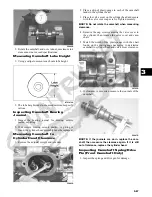
Reviews: