4-8
TESTING OIL PUMP PRESSURE (XTZ)
NOTE: The engine must be warmed up to operating
temperature (cooling fan cycling) for this test.
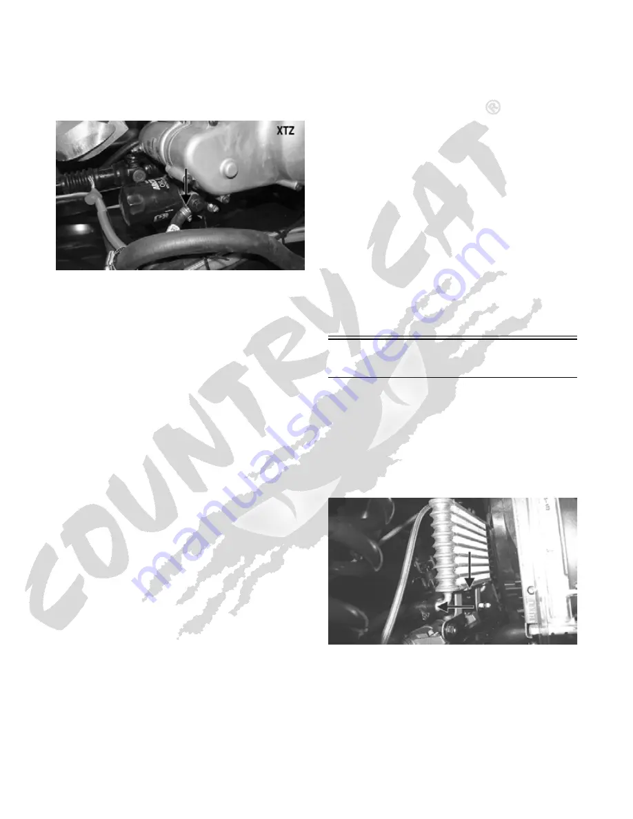
1. Remove both seats and center console; then remove
the oil hose from the fitting nearest the oil filter base.
PR617B
2. Using a suitable “T” fitting, connect Oil Pressure
Test Kit to the oil fitting and hose. Tighten all clamps
securely.
NOTE: Some oil seepage may occur when installing the
oil pressure gauge. Wipe up oil residue with a cloth.
3. Set the parking brake and start the engine. Allow the
engine to warm up to operating temperature (with
cooling fan cycling).
4. Set the speedometer/tachometer to RPM. With the
engine running at 3000 RPM, the pressure gauge
must show 1.05-1.2 kg/cm
2
(15-17 psi).
5. Remove the test kit from the vehicle and install the
oil hose. Tighten the clamps securely.
6. Install the seats, seat base, and center console as
required making sure the seats lock securely.
NOTE: If the oil pressure is lower than specified,
check for an oil leak, damaged oil seal, or defective
oil pump.
NOTE: If the oil pressure is higher than specified,
check for too heavy engine oil weight (see Section 1),
clogged oil passage, clogged oil filter, or improper
installation of the oil filter.
REMOVING/DISASSEMBLING
1. Remove the oil pump from the engine (see Left-Side
Components (XT/XTX) or Center Crankcase Com-
ponents (XTZ) in Section 3).
2. Remove the Phillips-head screw on the back side of
the pump and separate the pump housing and cover.
Note the position of the inner and outer rotors and
alignment pin for assembly.
3. Remove oil pump components.
CLEANING AND INSPECTING
NOTE: Whenever a part is worn excessively,
cracked, or damaged in any way, replacement is nec-
essary.
1. Clean all oil-pump components.
2. Inspect the rotors for scoring and gouges.
3. Inspect the alignment pin, driveshaft, and driven
sprocket for damage.
4. Inspect the pump housing and cover for cracks or
damage.
ASSEMBLING/INSTALLING
1. Place the rotors into the pump housing making sure
the alignment pin is in the groove of the rotor.
2. Place the cover onto the pump housing.
3. Secure the pump with the Phillips-head screw coated
with red Loctite #271. Tighten to 8 ft-lb.
4. Install the oil pump into the engine (see Left-Side
Components (XT/XTX) or Center Crankcase Com-
ponents (XTZ) in Section 3).
Oil Cooler (XTZ)
This model has an oil cooler in addition to the liquid
cooling system. An oil cooler kit may be installed on any
Arctic Cat ROV.
REMOVING
1. Loosen the clamps securing the oil hoses to the oil
cooler; then place a shallow pan or absorbent towel
under the connection and remove the hoses.
PR484A
2. Remove the flange nuts and cap screws from the oil
cooler mountings and remove the oil cooler.
Summary of Contents for 2013 Prowler XT
Page 1: ...Prowler XT XTX XTZ ...
Page 3: ......
Page 5: ......
Page 149: ...4 16 NOTES ...
Page 211: ...7 8 NOTES ...
Page 232: ...8 21 8 NOTES ...
Page 233: ... Printed in U S A Trademarks of Arctic Cat Inc Thief River Falls MN 56701 p n 2259 530 ...


