5-9
5
Electronic Power
Steering (EPS) (XTX)
The EPS system is an electro-mechanical device that utilizes
12 volt DC power to drive a motor linked to the steering
shaft to assist the driver when rotating the steering wheel.
Driver steering inputs are detected by a torque-sensing
transducer assembly within the EPS housing. These inputs
are converted to electronic signals by the transducer and
control circuitry to tell the motor which way to drive the
steering shaft. When no steering input (pressure on the steer-
ing wheel) is detected, no torque signal is generated, and no
steering assist is provided by the motor.
The EPS system is battery-system powered; therefore, the
battery must be in good condition and fully charged.
Power delivery and overload protection are provided by an
EPS relay and 30-amp fuse, located under the seat in the
Power Distribution Module (PDM).
If a system malfunction occurs, a diagnostic trouble code
(DTC) will flash on the LCD gauge until the condition is
corrected, the ignition key is cycled, or the EPS recovers.
The following is a list of conditions that can generate a
code.
NOTE: The EPS assembly is not serviceable and
must not be disassembled or EPS warranty will be
voided. Make sure to thoroughly troubleshoot the
entire system before replacing the EPS assembly.
The following tests may help in determining the source of
a code:
Condition: Ignition Key Switch ON and NO EPS assist
when moving the steering wheel. Code flashing.
NOTE: Prior to troubleshooting below, make sure
the Ignition Key Switch has not been left on with the
engine not started. After five minutes, this will deacti-
vate the EPS and display the code. Turn the Ignition
Key Switch OFF and back to ON to reset and reacti-
vate the EPS. If code and symptom persists, continue
as follows:
1. Check 30-amp EPS fuse.
2. Check EPS relay (may be switched with any other
4-pin relay on PDM - replace relay if EPS normal after
switching).
3. Disconnect 2-pin connector on the EPS assembly and
connect a volt meter set to DC voltage to the harness
(black meter lead to BLK and red meter lead to
ORG/BRN).With the ignition switch to the ON posi-
tion, the meter must read more than 8.5 DC volts (if
correct voltage is not present, check connections and
wiring harness - if correct voltage is present, replace
EPS assembly - see Steering/Frame/Controls).
If after completing the above checks with normal results
and a code persists, the EPS assembly must be replaced
(see Steering/Frame/Controls).
Ignition Switch
To access the ignition switch, dash switches, front acces-
sory connectors, and front switched accessory connector,
the dash must be unfastened and slid to the rear.
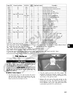
Code
Fault
Description
Possible Cause
Recovery Method
C1301 Over Current Internal EPS Condition
Correct EPS condi-
tion, then cycle key
switch On-Off-On
C1302 Excessive
Current Error
Internal EPS Condition
Correct EPS condi-
tion, then cycle key
switch On-Off-On
C1303 Torque Sen-
sor Range
Fault
Internal EPS Condition
Correct EPS condi-
tion, then cycle key
switch On-Off-On
C1304 Torque Sen-
sor Linearity
Fault
Internal EPS Condition
Correct EPS condi-
tion, then cycle key
switch On-Off-On
C1305 Rotor Posi-
tion Encoder
Internal EPS Condition
Correct EPS condi-
tion, then cycle key
switch On-Off-On
C1306 System Volt-
age Low
System voltage low (less
than 11 V DC at EPS). Wire
harness issue, faulty volt-
age regulator, weak battery,
or loose battery terminals.
EPS will auto-recover
when battery supply
returns to normal
C1307 System Volt-
age High
System voltage is high
(more than 16 V DC at
EPS). Wire harness issue,
faulty voltage regulator, or
loose battery terminals.
EPS will auto-recover
when the battery sup-
ply returns to normal
C1308 Temp Above
110° C
Clean EPS housing and
cooling fins.
EPS will auto-recover
when internal temp
drops below 150° C
C1309 Temp Above
120° C
Clean EPS housing and
cooling fins.
EPS will auto-recover
when internal temp
drops below 115° C
C1312 Vehicle
Speed
Broken CAN wires in main
harness, disconnected or
defective speed-sensor,
broken speed sensor wires.
EPS will auto-recover
when vehicle speed
signal returns to nor-
mal
C1315 Engine RPM Broken CAN wires in the
main harness.
EPS will auto-recover
when engine RPM
signal returns to nor-
mal
C1316 EEPROM
Error
Internal EPS condition
Correct EPS condi-
tion, then cycle key
switch On-Off-On
C1317 CAN Bus
Error
Broken CAN wires in main
harness. EFI ECM connec-
tor has been disconnected.
Correct EPS condi-
tion, then cycle key
switch On-Off-On
C1318 CRC Error
EPS reflash failed. Battery
power was lost or key switch
was turned off during EPS
reflash.
EPS must be repro-
grammed
C1319 Boot Counter
Exceeded
EPS reflash failed. Battery
power was lost or key switch
was turned off during EPS
reflash.
EPS must be repro-
grammed
C1323 “EPS OFF”
Gauge Dis-
play
EPS has been automatically
disabled after five minutes
of inactivity to conserve bat-
tery power.
EPS will auto-recover
when engine is
started or key switch
is cycled On-Off-On
C1324 Loss of CAN
communica-
tion with EPS
unit
Broken CAN wires in main
harness or disconnected
EPS. This is not an EPS
generated DTC; gauge DTC
display only.
Gauge DTC display
will clear when
EPS-to-gauge CAN
communication
restored.
CAUTION
Do not attempt to check resistance of the EPS motor (2-pin
input receptacle). There are internal capacitors holding a
charge that can cause internal damage to an ohmmeter.
Code
Fault
Description
Possible Cause
Recovery Method
Summary of Contents for 2013 Prowler XT
Page 1: ...Prowler XT XTX XTZ ...
Page 3: ......
Page 5: ......
Page 149: ...4 16 NOTES ...
Page 211: ...7 8 NOTES ...
Page 232: ...8 21 8 NOTES ...
Page 233: ... Printed in U S A Trademarks of Arctic Cat Inc Thief River Falls MN 56701 p n 2259 530 ...

