5-21
5
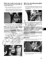
NOTE: Prior to testing the TPS, inspect the
three-wire plug connector on the main harness and
the three-pin plug on the TPS for contamination, bro-
ken pins, and/or corrosion.
2. Make sure the ignition switch is in the OFF position;
then select the DC Voltage position on the meter.
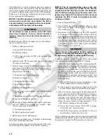
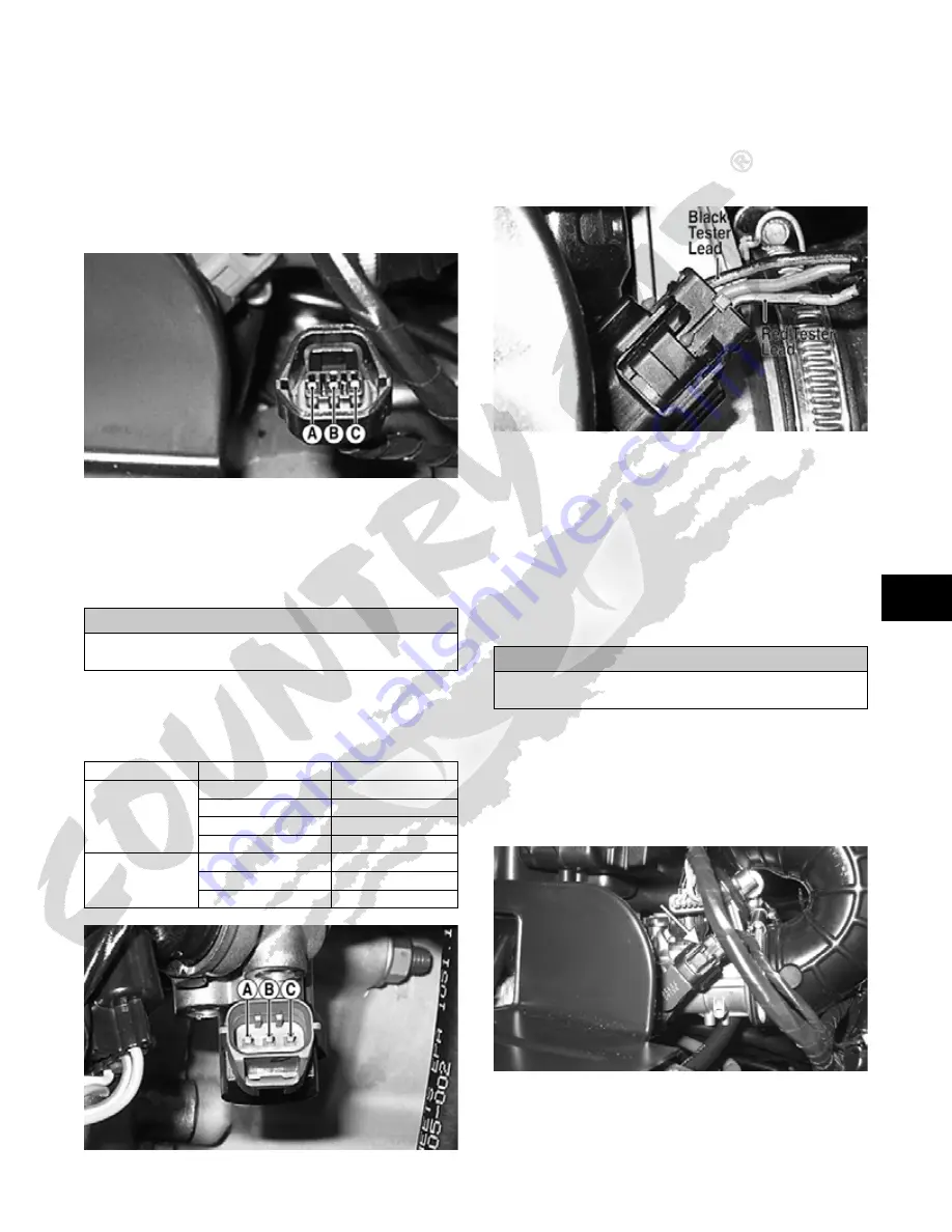
3. Connect the black tester lead to terminal A and the red
tester lead to terminal B. Turn the ignition switch to the
ON position. The meter should read 4.5-5.5 DC volts.
PR538A
4. Remove the black tester lead from terminal A and con-
nect it to terminal C. The meter should read 5.0 DC volts.
NOTE: If the meter does not read as specified,
check for poor connections at the ECM or open/bro-
ken wires in the wiring harness.
5. Turn the ignition switch to the OFF position.
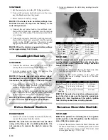
6. Select the OHMS position on the meter; then per-
form the following resistance tests on the TPS.
PR535A
NOTE: If any meter reading is not as specified,
replace or adjust the TPS (see INSTALLING/ADJUST-
ING in this sub-section).
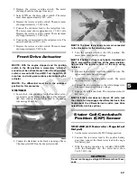
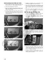
7. Connect the main harness TPS connector to the TPS;
then using MaxiClips, connect the black tester lead
to the black wire and the red tester lead to the
green/black wire.
PR546A
8. Select the DC Voltage position on the meter and turn
the ignition switch to the ON position. The meter
should read approximately 0.6 DC volt with the
throttle closed and approximately 5.0 DC volts with
the throttle in the full-open position.
NOTE: If the meter readings are as specified, check
the main harness connector at the ECM main harness
wiring. If the meter readings are not as specified,
replace the TPS and adjust to specifications (see
INSTALLING/ADJUSTING in this sub-section).
9. Clear all ECM error codes after servicing is complete
(see ECM Error Codes in this section).
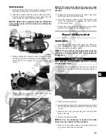
REMOVING
1. Remove the seats and center console; then discon-
nect the three-wire TPS connector plug.
PR533A
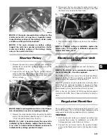
2. Remove the screw securing the TPS to the throttle
body and remove the TPS.
CAUTION
Always make sure the ignition switch is in the OFF posi-
tion before disconnecting the ECM.
Throttle Position
Pins
Ohms
Closed
A, B, or C to Ground
Infinity (Open)
A to B
5.0k
A to C
650
B to C
4.5k
Full-Open
A, B, or C to Ground
Infinity (Open)
A to C
3.8k
B to C
1.3k
CAUTION
Always make sure the ignition switch is in the OFF posi-
tion before disconnecting the ECM.
Summary of Contents for 2013 Prowler XT
Page 1: ...Prowler XT XTX XTZ ...
Page 3: ......
Page 5: ......
Page 149: ...4 16 NOTES ...
Page 211: ...7 8 NOTES ...
Page 232: ...8 21 8 NOTES ...
Page 233: ... Printed in U S A Trademarks of Arctic Cat Inc Thief River Falls MN 56701 p n 2259 530 ...


