6-15
6
AF897D
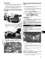
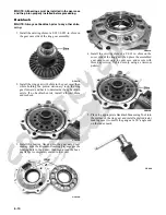
9. Install the brake calipers. Secure with new
“patch-lock” cap screws tightened to 20 ft-lb.
PR264A
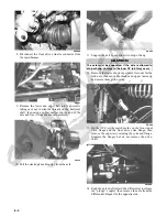
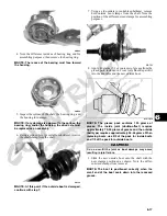
10. Connect the front drive actuator connector to the
main harness; then secure the wires to the frame with
nylon ties.
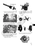
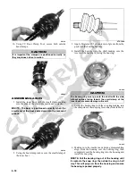
11. Apply a light coat of multi-purpose grease to the hub
splines; then install the hubs and nuts. Tighten to 200
ft-lb; then install new cotter pins.
PR256
12. Install the wheels and tighten in a crisscross pattern
in 20 ft-lb increments to 80 ft-lb (aluminum wheels)
or 45 ft-lb (steel wheels).
13. Remove the vehicle from the support stand.
14. Install the belly panel.
Drive Axles
REMOVING REAR DRIVE AXLE
1. Secure the vehicle on a support stand to elevate the
wheels.
2. Set the parking brake; then remove the wheels.
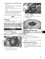
3. Remove the cotter pins securing the axle nuts; then
remove the nuts.
KX041
4. Slide the hub out of the knuckle and set aside.
PR221
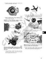
5. Remove the cap screw and lock nut securing the
knuckle to the upper A-arm. Discard the lock nut.
! WARNING
Make sure the vehicle is solidly supported on the sup-
port stand to avoid injury.
Summary of Contents for 2013 Prowler XT
Page 1: ...Prowler XT XTX XTZ ...
Page 3: ......
Page 5: ......
Page 149: ...4 16 NOTES ...
Page 211: ...7 8 NOTES ...
Page 232: ...8 21 8 NOTES ...
Page 233: ... Printed in U S A Trademarks of Arctic Cat Inc Thief River Falls MN 56701 p n 2259 530 ...


