8-6
PR766A
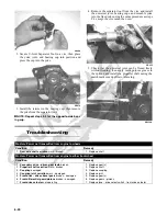
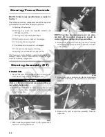
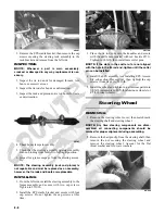
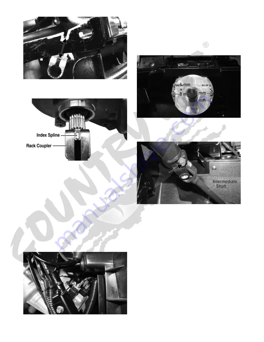
2. Rotate the EPS shaft to align the index (flattened)
spline with the slot in the rack coupler.
PR776A
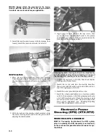
NOTE: Alignment need only be approximate as final
alignment is not possible until the EPS is engaged
with the coupler.
3. Install the EPS assembly into the coupler turning the
EPS shaft slightly to align the index spline; then seat
the EPS firmly onto the frame.
4. Install four cap screws securing the EPS assembly to
the frame and tighten to 35 ft-lb.
5. Install the cap screw in the EPS to rack coupler and
tighten to 11 ft-lb.
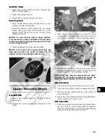
6. Connect the two electrical connectors; then align the
slot in the intermediate steering shaft coupler to the
index (flattened) spline on the EPS input shaft and
install. Install but do not tighten the cap screw.
PR759B
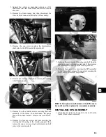
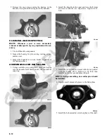
7. Install the steering shaft housing with steering shaft
connecting the steering shaft and intermediate shaft
first; then slide the housing into place on the steering
support.
8. Secure the steering shaft housing to the frame with
four cap screws and nuts. Tighten the 6 mm nuts to 8
ft-lb and the 8 mm nuts to 20 ft-lb.
PR764B
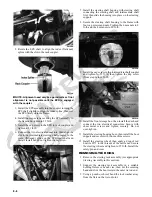
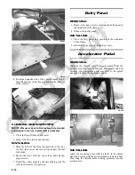
9. Install the cap screw in the intermediate shaft coupler
and tighten to 31 ft-lb; then tighten the cap screw
(from step 6) to 11 ft-lb.
PR765A
10. Install the front storage box; then install the dash and
connect the two electrical connectors. Secure with
sheet metal screws and tighten securely. Do not
over-tighten.
11. Install the steering housing boot; then install the boot
support and secure with two machine screws.
12. Install the steering wheel; then apply a drop of red
Loctite #271 to the threads of the castle nut. Secure
the steering wheel and tighten to 25 ft-lb. Install the
safety pin and cover.
REMOVING TIE RODS
1. Remove the steering rack assembly (see appropriate
Steering Assembly in this section).
2. Support the steering rack assembly in a suitable
holding fixture or bench vise; then cut the securing
band and slide the boot toward the outer tie rod end.
3. Using a punch or chisel, bend the lock washer away
from the flats on the tie rod joint.
Summary of Contents for 2013 Prowler XT
Page 1: ...Prowler XT XTX XTZ ...
Page 3: ......
Page 5: ......
Page 149: ...4 16 NOTES ...
Page 211: ...7 8 NOTES ...
Page 232: ...8 21 8 NOTES ...
Page 233: ... Printed in U S A Trademarks of Arctic Cat Inc Thief River Falls MN 56701 p n 2259 530 ...

