2-15
2
CD963
CD966A
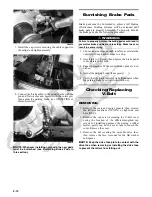
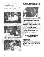
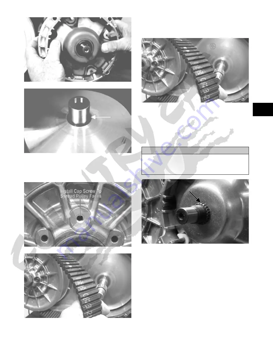
4. Install one of the V-belt cover cap screws into the
driven pulley fixed face; then turn the cap screw
clockwise to spread the pulley faces. Remove the
V-belt.
PR476A
GZ085
INSTALLING
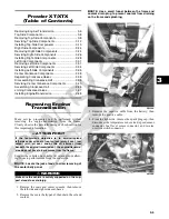
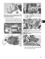
1. Place the V-belt into position on the driven pulley
and over the front shaft.
GZ085
NOTE: The arrows on the V-belt should point in the
direction of engine rotation.
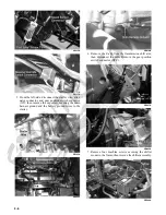
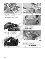
2. Pinch the V-belt together near its center and slide the
spacer and movable drive face onto the driveshaft.
Secure the drive face with a washer and nut (coated
with red Loctite #271). Tighten the nut to 165 ft-lb.
GZ485A
NOTE: At this point, remove the cap screw from the
driven pulley face.
3. Rotate the V-belt and driven pulley/clutch until the
V-belt is flush with the top of the driven pulley.
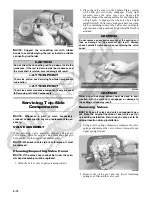
4. Place the V-belt cover gasket into position; then
install the cover and secure with the cap screws mak-
ing sure the different-lengthed cap screws are in their
proper location. Tighten the cap screws to 8 ft-lb.
5. Secure the seat-base with the four cap screws.
Tighten securely.
6. Install the seats and center console making sure the
seats lock securely.
CAUTION
Make sure the movable drive face plate is fully engaged onto
the splines of the clutch shaft before tightening the nut or
false torque readings may occur. This will cause the assem-
bly to loosen damaging the shaft and clutch face plate.
Summary of Contents for 2013 Prowler XT
Page 1: ...Prowler XT XTX XTZ ...
Page 3: ......
Page 5: ......
Page 149: ...4 16 NOTES ...
Page 211: ...7 8 NOTES ...
Page 232: ...8 21 8 NOTES ...
Page 233: ... Printed in U S A Trademarks of Arctic Cat Inc Thief River Falls MN 56701 p n 2259 530 ...


