3-9
3
CC001D
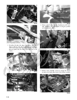
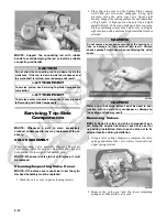
NOTE: Keep the mounting hardware with the covers
for assembly purposes or thread them back into the
head to keep them separated.
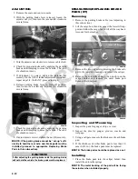
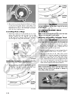
2. Remove the 12 cap screws securing the valve cover
to the head; account for the four rubber washers on
the top side cap screws. Remove the valve cover.
Account for and note the orientation of the cylinder
head plug. Note the location of two alignment pins.
CD205
CD206
CD211A
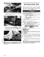
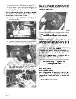
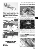
3. Loosen the cap screw on the end of the tensioner;
then remove the two cap screws securing the ten-
sioner adjuster assembly and remove the assembly.
Account for a gasket.
CC009D
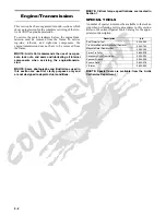
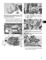
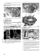
4. Using an awl, rotate the C-ring in its groove until it is
out of the cylinder head; then remove the C-ring.
NOTE: Care should be taken not to drop the C-ring
down into the crankcase.
CC012D
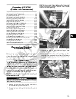
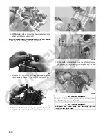
5. Bend the washer tabs down and remove the two cap
screws securing the sprocket to the camshaft; then
drop the sprocket off the camshaft.
Summary of Contents for 2013 Prowler XT
Page 1: ...Prowler XT XTX XTZ ...
Page 3: ......
Page 5: ......
Page 149: ...4 16 NOTES ...
Page 211: ...7 8 NOTES ...
Page 232: ...8 21 8 NOTES ...
Page 233: ... Printed in U S A Trademarks of Arctic Cat Inc Thief River Falls MN 56701 p n 2259 530 ...


