3-35
3
INSPECTING OIL PUMP
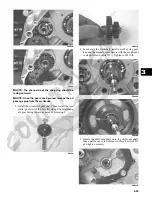
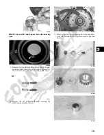
1. Inspect the pump for damage.
2. It is inadvisable to remove the screw securing the
pump halves. If the oil pump is damaged, it must be
replaced.
CD988A
DRIVEN PULLEY
NOTE: The driven pulley is a non-serviceable com-
ponent. If pulley faces, cam ramps, or sheave bush-
ings are worn, the assembly must be replaced. Do not
to disassemble the driven pulley.
Installing Left-Side
Components
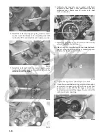
1. Install the gear position switch making sure the two
neutral contact pins and the two springs (XT only)
are properly positioned. Tighten the cap screws
securely.
CD997
CD994
2. Install the secondary shaft bearing housing making
sure the two alignment pins are properly positioned.
Tighten the cap screws to 28 ft-lb.
CD999
3. Install the oil pump onto the engine; then tighten the
cap screws securely.
CD988
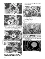
4. Install the oil pump drive gear spacer onto the crank
balancer shaft. Grease the pin and insert it into the
shaft; then install the drive gear making sure the
raised side of the gear is facing toward the inside.
Secure the gear with the cap screw (threads coated
with red Loctite #271) and the washer. Tighten the
cap screw to 62 ft-lb.
XT
Summary of Contents for 2013 Prowler XT
Page 1: ...Prowler XT XTX XTZ ...
Page 3: ......
Page 5: ......
Page 149: ...4 16 NOTES ...
Page 211: ...7 8 NOTES ...
Page 232: ...8 21 8 NOTES ...
Page 233: ... Printed in U S A Trademarks of Arctic Cat Inc Thief River Falls MN 56701 p n 2259 530 ...


