37
FC030
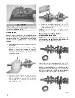
NOTE: For assembling purposes, note the rout-
ing of the oil-injection hoses.
12. Remove the three cap screws securing the thermostat
cap; then remove the cap and thermostat.
FC032
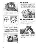
13. Remove the six screws securing the water pump
cover to the crankcase and remove the cover.
Account for the O-ring gasket and the alignment
pins.
14. Remove the cap screw securing the water pump
impeller; then slide the impeller free of the shaft.
15. Remove the union cap screw securing the check
valve assembly to the crankcase; then remove the
two screws securing the oil-injection pump.
Remove the pump, retainer, and O-ring.
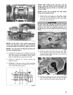
FC031
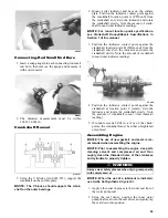
16. Turn the engine upside down on support blocks
and remove the coolant temperature sensor switch.
FC033
17. With its bottom side up on two support blocks,
remove the cap screws securing the crankcase
halves.
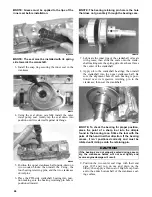
18. Separate the crankcase halves by installing two
crankcase cap screws in opposite corners leaving
the heads approximately 6 mm (1/4 in.) out. Using
a plastic hammer and lifting on the ends of the
crankshaft, tap on each cap screw head until the
case halves separate. Remove the cap screws.
FC034
19. Lift the bottom half of the crankcase off the top
half and account for the crankcase dowel pins.
20. Lift the crankshaft free from the top half of the
crankcase and slide the crankshaft oil seals off the
crankshaft. Account for the C-ring. Remove the
bearing retaining pins.
NOTE: The end bearings are not pressed onto
the crankshaft. After removing the seals, use care
not to allow the bearings to slide off the crank-
shaft.
21. Remove the oil-injection pump/water pump drive-
shaft from the lower crankcase half. Account for
the thrust washer on the outer end of the shaft.
CAUTION
DO NOT drive any tool between halves to separate the
crankcase. Damage to the sealing surfaces will result.
CAUTION
Care must be taken to not allow the connecting rods to
drop onto the sealing surface of the bottom case half.
Summary of Contents for 2014 SNO PRO 500
Page 1: ...SNO PRO 500 ...
Page 16: ...12 Wiring Diagram Hood Harness p n 1686 587 0744 201 ...
Page 17: ...Wiring Diagram Ignition Main Harness p n 1686 628 0745 605 13 ...
Page 18: ...14 NOTES ...
Page 89: ......
Page 90: ...Printed in U S A Trademarks of Arctic Cat Inc Thief River Falls MN 56701 p n 2259 778 ...


