48
726-306A
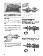
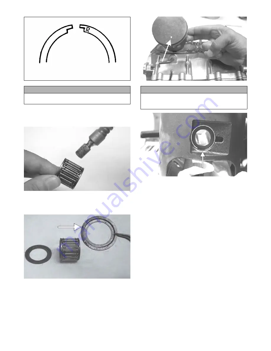
26. Apply oil to the connecting-rod small end bear-
ings; then install the small-end bearings. Install a
washer on each side of the connecting rod.
TZ068
NOTE: The shoulder side of the washer must
seat to the needle bearing.
CM172A
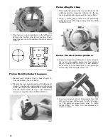
27. On each piston, install a circlip into the opposite
side from which the piston will be installed.
28. Place each piston over the connecting rod so the
indicator dot on each piston will point toward the
intake/exhaust ports; then install an oiled piston
pin and the remaining circlip.
NOTE: The indicator dot is found on the piston
dome top.
FC079A
CM195B
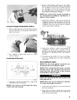
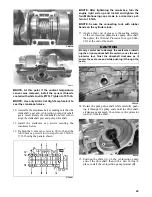
29. Rotate each piston ring until the ring ends are
properly positioned on either side of the ring
keeper; then apply oil to the piston assemblies and
cylinder bores. Remove the rubber bands or hoses
from the connecting rods.
30. Install the dowel pins into the crankcase; then
place the cylinder base gasket into position on the
crankcase.
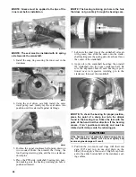
31. In turn on each cylinder, place a piston holder (or
suitable substitute) beneath the piston skirt and
square the piston in respect to the crankcase; then
using a ring compressor or the fingers, compress
the rings and slide the cylinder over the piston.
Remove the piston holder and seat the cylinder
firmly onto the crankcase.
NOTE: The cylinders should slide on easily. DO
NOT force the cylinders on.
CAUTION
Incorrect installation of the piston rings will result in
engine damage.
CAUTION
Make sure the circlips are firmly seated and the open
end is directed either up or down before continuing
with assembly.
Summary of Contents for 2014 SNO PRO 500
Page 1: ...SNO PRO 500 ...
Page 16: ...12 Wiring Diagram Hood Harness p n 1686 587 0744 201 ...
Page 17: ...Wiring Diagram Ignition Main Harness p n 1686 628 0745 605 13 ...
Page 18: ...14 NOTES ...
Page 89: ......
Page 90: ...Printed in U S A Trademarks of Arctic Cat Inc Thief River Falls MN 56701 p n 2259 778 ...


