107
KC314
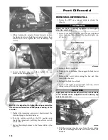
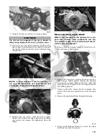
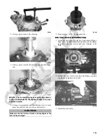
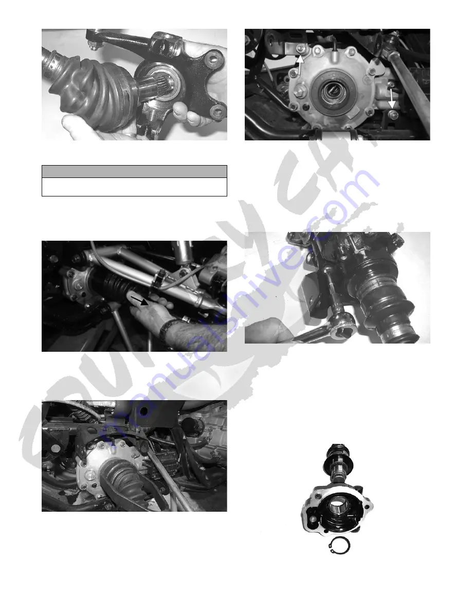
9. Support the axle to not allow it to drop or hang.
10. Pull out on the axle until completely extended; then
push it back in approximately one half inch and pull
out sharply. Repeat until axle spline dislodges from
the gear case.
KC425A
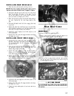
NOTE: In some instances it may be necessary to
use a pry-bar between the gear case housing and
axle coupler shoulder to dislodge the splines.
KC486
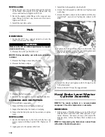
11. Remove the cap screws from the drive coupler
flange; then remove the upper and lower mounting
cap screws and remove the differential from the
frame.
KC488A
Disassembling Input Shaft
NOTE: This procedure can be performed on a rear
gear case; however, some components may vary
from model to model. The technician should use dis-
cretion and sound judgment.
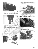
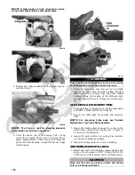
1. Remove the cap screws securing the front drive actu-
ator and remove the actuator.
CD102
2. Remove the cap screws securing the pinion housing;
then using a rubber mallet, remove the housing.
Account for a gasket. Remove the fork, collar, and
spring. Note the location of all the components for
assembling purposes.
3. Using a side-cutter, remove the boot clamps; then
remove the boots and splined drive from the input
shaft.
4. Remove the input shaft from the pinion housing.
CD107
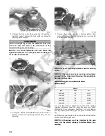
5. Using the Multi-Seal Remover, remove the input
shaft seal. Account for a spacer.
CAUTION
The axle must be supported. If the axle is allowed to
drop or hang, damage to the inner CV joint may occur.

