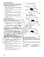
66
MD1313
Disassembling Crankcase
Half
NOTE: To aid in installing, it is recommended that
the assemblies be kept together and in order.
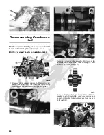
NOTE: For steps 1-6, refer to illustration FI639A.
FI639A
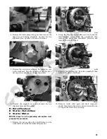
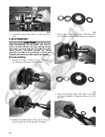
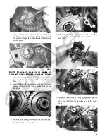
1. Remove the secondary driven shaft assembly (A)
noting the location of the front and rear bearing
locating pins and the center bearing locating ring.
FI660A
FI659A
FI661A
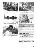
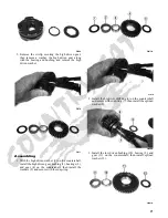
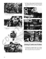
2. Remove the reverse idler assembly (B). Account for
and note the location of the inner bushing (1), idler
shaft (2), and outer washer (3).
FI641A
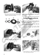
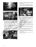
3. Remove the driveshaft (C); then pull the shift fork
locating shaft (D) out of the crankcase locating boss
and allow the shift forks to disengage from the gear
shift shaft (F).
FI646


