74
ROV374
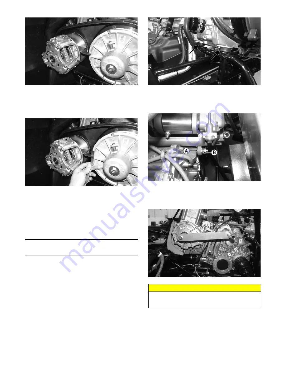
2. The bar should just clear the outside edge of the sta-
tionary sheave of the driven clutch with a maximum
of 0.76 mm (0.030 in.) clearance. If the bar will not
clear the outside edge or clearance is more than the
specified amount, the alignment must be corrected.
ROV375
NOTE: If alignment must be corrected, add or
remove the appropriate alignment shim (p/n 1423-189
– 1.02 mm) or (p/n 1423-219 – 0.51 mm).
3. Repeat steps 1 and 2 as required until correct align-
ment is achieved.
NOTE: To install left-side components, see Engine –
Installing Engine.
Installing Engine
NOTE: The driveshaft must be secured to the tran-
saxle before the engine is installed.
NOTE: If removed, install the engine/transaxle
mounting brackets to the rear of the engine; then
install the front rubber engine mounts to the front
engine brackets. Secure the front engine brackets to
the front of the crankcase assembly.
1. Using a proper lifting device, install the front engine
mount studs into the frame. In the chassis, install the
new lock nuts but do not tighten at this time.
WT515A
2. Align and install the cap screws securing the engine
to the transaxle. Account for a spacing washer (A).
Apply anti-seize compound to the threads of the
adjuster nut (B) but do not tighten at this time.
WT474A
3. Using Drive and Driven Clutch Center to Center
Tool, install the tool over the output shaft of the tran-
saxle and using the cap screw provided and secure it
to the crankshaft.
WT475
4. With the jam nut loosened towards the shoulder of
the adjuster nut, tighten the adjuster nut (A) to 10
ft-lb and then the jam nut (B) to 15 ft-lb.
CAUTION
Care should be taken to install the tool over the output
shaft and slide the tool evenly towards the crankshaft to
avoid damaging the shaft.


