94
1. Disconnect the coil connector. Connect the red tester
lead to one coil terminal; then connect the black tes-
ter lead to the other coil terminal.
2. Resistance must be less than 1 ohm.
NOTE: If the meter does not show as specified,
replace ignition coil.
NOTE: Secondary coil resistance checks are not rec-
ommended. An internal diode in the coil prevents
accurate secondary resistance measurements.
Spark Plug Cap
1. Connect the red tester lead to one end of the cap;
then connect the black tester lead to the other end of
the cap.
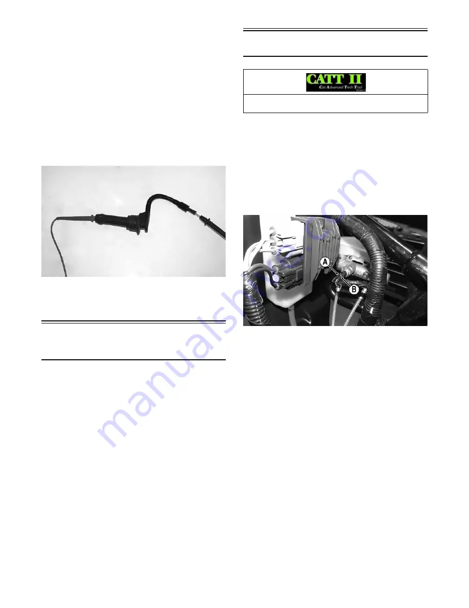
WT553
2. The meter must show 5000 ohms.
NOTE: If the meter does not show as specified,
replace the spark plug cap.
Accessory
Receptacle/Connector
NOTE: This test procedure is for either the recepta-
cles or the connectors.
VOLTAGE
1. Turn the ignition switch to the ON position; then set
the meter selector to the DC Voltage position.
2. Connect the red tester lead to the positive connector;
then connect the black tester lead to the negative
connector.
3. The meter must show battery voltage.
NOTE: If the meter shows no battery voltage, trou-
bleshoot the fuse, receptacle, connector, or the main
wiring harness.
Switches
The switch connectors are spade-type connectors on the
side of the master cylinder.
NOTE: The ignition switch must be in the ON posi-
tion.
VOLTAGE (Brakelight)
1. Set the meter selector to the DC Voltage position.
2. Connect the red tester lead to the orange wire (B);
then connect the black tester lead to the red/blue wire
(A).
WT556A
3. The meter must show battery voltage.
NOTE: If the meter shows no battery voltage, trou-
bleshoot the fuse, switch, or the main wiring harness.
NOTE: If the meter shows battery voltage, the main
wiring harness is good; proceed to test the
switch/component and the connector.
RESISTANCE (Brakelight)
NOTE: The brake pedal must be depressed for this
test.
1. Set the meter selector to the OHMS position.
2. Connect the red tester lead to one terminal; then con-
nect the black tester lead to the other terminal.
3. When the pedal is depressed, the meter must show
less than 1 ohm.
NOTE: If the meter shows more than 1 ohm of resis-
tance, replace the switch.
VOLTAGE (Headlight)
1. Connect the red meter lead to the red/black wire;
then connect the black meter lead to the black wire.
2. Turn the ignition switch to the ON position. The
meter must show battery voltage.
Component data can be retrieved using the CATT II. Uti-
lize the Sensor Data screen.


