background image

8

RIGGING

Always spool out as much wire cable as possible when preparing rigging.
Pick an anchor as far away as practical. This provides the winch with its
greatest pulling power. 
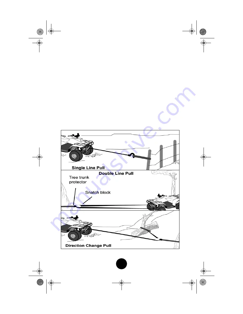
Rigging a double line with a snatch block will reduce the load on the winch
to half without significant loss of spooling speed.
Natural anchors such as trees, stumps, and rocks are the handiest when avail-
able. Attach the choker chain, wire choker rope, or tree trunk protector on
the anchor as low as possible to avoid pulling the anchor down. If several
possible anchors are available but they are not strong enough individually, it
may be practical to attach a wire or chain choker around several anchors to
form a strong collective anchor point.

Pulling Power

Wire Cable Layer

3000 lb (1360 kg)

1st layer closest to drum core

2580 lb (1170 kg)

2nd layer

2220 lb (1007 kg)

3rd layer

1910 lb (866 kg)

4th layer

• Some of the most commonly used riggings are shown below.

3000 lb winch eng.fm  Page 8  Wednesday, August 27, 2014  2:59 PM


Summary of Contents for 2260-452

Page 1: ...1 Operator s Manual Installation Instructions Replacement Parts List TREUIL 3000 p n 2260 452 n p 2260 452 2014 Arctic Cat Inc Marques déposées d Arctic Cat Inc Thief River Falls MN 56701 3000 WINCH Manuel de l opérateur Instructions d installation Liste des pièces de rechange ...

Page 2: ...ed by accident abuse misuse collision overloading exhaust or misapplication or has been improperly serviced The finish and synthetic rope on the winch are excluded from warranty In addition commercial or industrial use or applica tion or any hoisting application voids the entire warranty In consideration of the foregoing any implied warranty is limited in duration to the various warranty periods s...

Page 3: ...eep hands clear of wire cable hook and fairlead opening during operation and when spooling Stand clear of wire cable and load during operation Keep others away Always inspect winch installation and wire cable condition before operating winch Do not exceed winch rated capacity Never touch wire cable or hook while in tension 3000 lb winch eng fm Page 1 Wednesday August 27 2014 2 59 PM ...

Page 4: ...Y AND PROPERTY DAMAGE Do not use winch to secure a load during transport Do not submerge in water Do not use to tow other vehicles Maximum single line pulling capacity 3000 lb 1360 kg Intermittent duty rating 12 Volts DC Use only 3 16 in 4 8 mm 7 x 19 aircraft wire cable 3000 lb winch eng fm Page 2 Wednesday August 27 2014 2 59 PM ...

Page 5: ...two to three feet of cable from the winch reel 2 Turn the winch selector knob to the engaged position then insert the ignition key into the ignition switch and turn to the ON position 3 Place the winch control in the IN position and observe the movement of the winch cable If the cable does not wind onto the reel in the proper direction reverse the lead connections on the winch motor terminals and ...

Page 6: ...tall speed a very rapid heat build up occurs which may cause motor damage To judge safe running time stop winching and lay your hand on the motor If the tem perature is uncomfortable shut down and cool the motor This can be used as an opportunity to recharge the battery Double line rigging will reduce the amperage draw from the motor allowing longer continual use see Rigging sub section BATTERY RE...

Page 7: ...n and tight wire wrap around the drum Failure to do so will cause binding and possible damage to the wire cable Spooling Out Freespooling is generally the quickest and easiest way to spool out wire cable Before freespooling wire cable from the winch power out enough cable to remove any cable tension then turn the winch selector knob to the freespool position Manually freespool out enough wire cabl...

Page 8: ...eed the winch and wire cable ratings When powering in wire cable during side pull operations the wire cable will stack up at one end of the drum Eventually this stack will become large enough to cause serious damage to the winch To prevent damage WARNING TO AVOID INJURY AND PROPERTY DAMAGE Wear heavy leather gloves when handling wire cable Never winch with less than 5 wraps of wire cable around dr...

Page 9: ...ny wire cable on the drum is tightly and evenly layered Spool enough wire cable to complete the next full layer on the drum Tighten and straighten the layer Repeat process until the hook is a minimum of 4 ft 1 2 m from the fairlead Spool in the remainder for storage SPOOLING REMAINDER FOR STORAGE Keep hands clear of wire cable hook and fairlead opening Always use the hook strap to hold hook when s...

Page 10: ... choker chain wire choker rope or tree trunk protector on the anchor as low as possible to avoid pulling the anchor down If several possible anchors are available but they are not strong enough individually it may be practical to attach a wire or chain choker around several anchors to form a strong collective anchor point Pulling Power Wire Cable Layer 3000 lb 1360 kg 1st layer closest to drum cor...

Page 11: ...3 Terminal Boot 8400 820 4 Cap Screw M8 x 20 Gr 8 8 8051 247 4 Spring Lock Washer 0 314 x 0 593 x 0 097 1541 361 1 Winch Hook w Strap Black 1441 130 1 Clevis Pin 1441 129 1 Cotter Pin 1441 424 1 Winch Hook Strap 0409 066 1 Solenoid 8476 625 2 Machine Screw M6 x 25 0623 038 2 Hex Nut w Washer 1441 176 4 Hex Nut M6 Solenoid NIC 1441 177 4 Spring Washer M6 Solenoid NIC 0409 176 1 Winch Switch Backlit...

Page 12: ...o it will spool from the bottom of the reel Loosely secure the winch A to the back side of the bumper plate with the two M8 x 20 Cap Screws C and Lock Washers D into the two upper bumper plate mounting holes Do not tighten at this time WARNING Always disconnect the negative battery cable first CAUTION Remove the bottom tie screw securing the winch together or damage to the cable rope may occur Thi...

Page 13: ...ob to the freespool position Pull the cable loop through the bumper plate and roller fairlead until the loop is clear of the roller fairlead approximately 3 4 in then turn the selector knob to the ENGAGED position 7 Place the clevis end of the tow hook onto the winch cable loop and secure with the clevis pin then using a hammer force the cotter pin through the clevis pin The cotter pin will spread...

Page 14: ...plug on the solenoid is facing toward the engine Using two M6 x 25 Torx Head Machine Screws and M6 Hex Nuts w Washers secure the solenoid to the electrical panel NOTE Loosening the battery box will aid in the installation of the solenoid The battery box does not need to be removed 4 Connect the Solenoid Adapter Harness to the solenoid INSTALLING CONSOLE WINCH SWITCH 1 Remove the right side plug fr...

Page 15: ... place Panel Template below and cut out the shaded area or install Switch Mount Panel Kit p n 1436 008 next to the existing panel on the dash making sure nothing is behind the cutting area 3000 lb winch eng fm Page 13 Wednesday August 27 2014 2 59 PM ...

Page 16: ...e wire pin plug on one side and the black wire receiver plug on the opposite side to the console harness NOTE The black wire pin plug is not used for this application If the black and orange two prong molded plug is needed for another accessory it will be necessary to install Adapter Plug p n 0686 131 which is not provided with this kit 6 Route the switch control harness wires along the main vehic...

Page 17: ...e upper cross tube on the frame and to the left side of the vehicle then along the top of the left upper frame tube Continue routing the cables downward along the frame tube to the main switch harness Continue routing the cables along the har nesses to the solenoid Secure cables and wires with cable ties UTV 055 WARNING FIRE HAZARD Failure to observe these instructions could lead to severe injury ...

Page 18: ... the electrical panel and follow the positive cable to the battery box 6 Install the battery making sure to connect the battery vent tube to the battery Secure the positive battery cable and the 36 in red lead to the positive battery post Tighten securely 7 Secure the negative battery cable the 36 in black cable and the sole noid adapter harness ground to the negative battery post Tighten securely...

Page 19: ...17 NOTES 3000 lb winch eng fm Page 17 Wednesday August 27 2014 2 59 PM ...

Page 20: ...18 3000 lb winch eng fm Page 18 Wednesday August 27 2014 2 59 PM ...

Page 21: ...uivez le câble positif allant à la boîte de batterie 6 Installez la batterie en vous assurant de brancher le tube de ventilation de la batterie Fixez le câble positif de la batterie et le fil rouge de 36 po au pôle de la batterie positif Serrez bien le tout 7 Fixez le câble négatif de la batterie le câble noir de 36 po et le borne de harnais d adapteur solénoïde au pôle négatif de la batterie Serr...

Page 22: ... du côté gauche du véhicule puis routez les le long du haut du tube de châssis supérieur gauche Continuez à routez les câbles vers le bas le long de tube du châssis vers le harnais de douille et le harnais prin cipal Continuez à routez les câbles le long des harnais allant au solénoïde UTV 055 AVERTISSEMENT RISQUE D INCENDIE De faillir à suivre ces instructions pour causer de graves blessures ou l...

Page 23: ... 0686 131 qui n est pas compris dans la trousse 6 Acheminer les fils du harnais de commande de commutateur le long de la principale faisceau du véhicule de la jauge dans le tableau de bord et le long de la côté gauche du cadre Les fils de commande de commutateur de harnais continuent en arrière le long du faisceau principal et pénètre sous le siège côté opérateur avec le câble de démarrage rouge 7...

Page 24: ...treuil dans la tableau de bord Faites trou ver la prise moulée à deux broches avec un fil orange et un fil noir situé sur le harnais de console en avant du commutateur d allumage dans la tableau de bord Branchez le harnais de commande d interrup teur dans la prise moulée ATTENTION Le guidon de frein de stationnement doit être retiré pour les modèles Prowler applicable situé sur la tableau de bord ...

Page 25: ...u il se fixe en posi tion REMARQUE N utilisez pas de force extrême Il n y a besoin que d un peu de force pour l insérer UTV 057 REMARQUE Si tous les positions pour interrupteurs sont déja utillisées placer le Gabarit du Paneau dessous et découper la zone grise ou installer la trousse de Paneau pour Montage D interrupteur n p 1436 008 et placer à côté du paneau existant Prenez soins que rien soit e...

Page 26: ...l aide d une mèche de perçage de 7 mm 9 32 po percez les trous de montage dans le panneau 3 Placez les onglets de montage du solénoïde sur les trous de montage dans le panneau en vous assurant que le raccord à fils du solénoïde est orienté vers la moteur En utilisant deux Vis mécanique torx de M6 x 25 et Écrous hexadécimal avec rondelles de M6 fixez le solénoïde au panneau élec trique REMARQUE Si ...

Page 27: ...âble qui se trouvant attachées au câble pour toute référence future 6 Tournez le bras du sélecteur en position FREESPOOL roulement libre Tirez la boucle de câble à travers la plaque du pare chocs et guide câble de rouleau jusqu à ce que la boucle dépasse la guide câble de rou leau de 3 à 4 pouces puis tournez le bras du sélecteur en position ENGAGED engagée 7 Placez l extrémité de chape de crochet...

Page 28: ...en position pour puisse se défasse de la base du rou leau Fixez le treuil A de marière lâche au côté arrière de la plaque de pare chocs avec les deux Vis à tête M8 x 20 C et les rondelles de res sort D dans les deux trous de montage de la plaque de pare chocs supé rieur Ne serrez pas pour le moment AVERTISSEMENT Débranchez toujours le câble négatif de la batterie en premier ATTENTION Retirez la vi...

Page 29: ...ge 0441 060 3 Protecteur de borne 8400 820 4 Cap Screw M8 x 20 Gr 8 8 8051 247 4 Spring Lock Washer 0 314 x 0 593 x 0 097 1541 361 1 Winch Hook w Strap Black 1441 130 1 Clevis Pin 1441 129 1 Cotter Pin 1441 424 1 Winch Hook Strap 0409 066 1 Solénoïde 8476 625 2 Vis mécanique torx M6 x 25 0623 038 2 Écrou hexadécimal avec rondelle 1441 176 4 Hex Nut M6 Solenoid NIC 1441 177 4 Spring Washer M6 Solen...

Page 30: ...9 3000 lb winch french fm Page 9 Wednesday August 27 2014 3 01 PM ...

Page 31: ...t pas assez solides individuellement vous pouvez les réunir en faisant un noeud coulant avec un câble ou une chaîne afin de constituer un puissant point d ancrage collectif Puissance de traction Couche de câble 1360 kg 3000 lb La 1ière couche la plus proche du centre du tambour 1170 kg 2580 lb 2 ième couche 1007 kg 2220 lb 3 ième couche 866 kg 1910 lb 4 ième couche Vous trouverez certains types de...

Page 32: ... crochet avec son cordon en appliquant une tension aussi constante que possible sur le câble Tout en maintenant la tension il devra se déplacer en direction du treuil pendant que vous actionnez l interrupteur de commande pour enrouler le câble Relâchez l interrupteur lorsque le crochet parvient à une distance minimale de 1 2 m 4 pi de l ouverture du cintre à rouleau Enroulez le reste du câble Enro...

Page 33: ...e pour l opération de treuillage AVERTISSEMENT AFIN D ÉVITER DES BLESSURES ET DES DOMMAGES MATÉRIELS Portez des gants de cuir résistants lorsque vous manipulez le câble métallique N utilisez jamais le treuil avec moins de 5 boucles de câble enroulées autour du tambour AVERTISSEMENT POUR PRÉVENIR DE GRAVES BLESSURES Éloignez les mains du câble du crochet et de l ouverture du cintre à rouleau pendan...

Page 34: ...it être embobiné sur son tambour sous une charge d au moins 227 kg 500 lb Débobinez le câble métallique aux 5 derniers enroulements du tambour ensuite activez le câble métallique sous une charge de 227 kg 500 lb ou plus REMARQUE Étirez le nouveau câble métallique aidera à créer un bobinage égal et serré autour du tambour Faillir à faire ainsi causera au câble métallique de s emmêler et causera un ...

Page 35: ...rmittent Ne le faites pas fonctionner en mettant le moteur à bas régime Lorsque le moteur du treuil atteint une vitesse si faible qu il peut caler il se met à surchauffer très rap idement ce qui peut l endommager Pour juger de la durée de fonc tionnement encore possible arrêter le treuil et posez la main sur le moteur Si la température est trop élevée au toucher arrêtez le moteur pour le laisser r...

Page 36: ...omatique du treuil 2 Tournez le bouton de sélection de treuil à la position d embrayage ensuite insérez la clé d allumage dans l interrupteur d allumage et tournez à la position en marche 3 Placez la commande du treuil à la position IN et observez le mouvement du câble de treuil Si le câble ne s embobine pas sur l enrouleur automatique dans le sens approprié inversez les connexions de fils de sort...

Page 37: ... DES DOMMAGES MATÉRIELS N utilisez pas le treuil pour maintenir un charge pendant le transport Ne le submergez pas dans l eau Ne l utilisez pas pour remorquer d autres véhicules Capacité de traction maximale à ligne simple 1360 kg 3000 lb Service intermittent 12 volts c c Utilisez du câble métallique d aviation de 4 8 mm 3 16 po 7 x 19 uniquement 3000 lb winch french fm Page 2 Wednesday August 27 ...

Page 38: ...e du cintre à rouleau pendant l utilisation du treuil et lors du rembobinage du câble Tenez vous à l écart du câble métallique et du chargement durant l utilisation Ne laissez personne s approcher Inspectez toujours l installation du treuil et l état du câble métallique avant de faire fonctionner le treuil N excédez pas la capacité nominale du treuil Ne touchez jamais le câble métallique ni le cro...

Page 39: ... si le treuil a été endommagé par accident abus collision surcharge échappement ou mauvaise ou a été mal entretenu La finition et corde synthétique sur le treuil sont exclus de la garantie En outre l utilisation commerciale ou industrielle ou une application ou une application de levage annule la totalité de la garantie En considération de ce qui précède toute garantie implicite est limitée dans l...

Reviews: