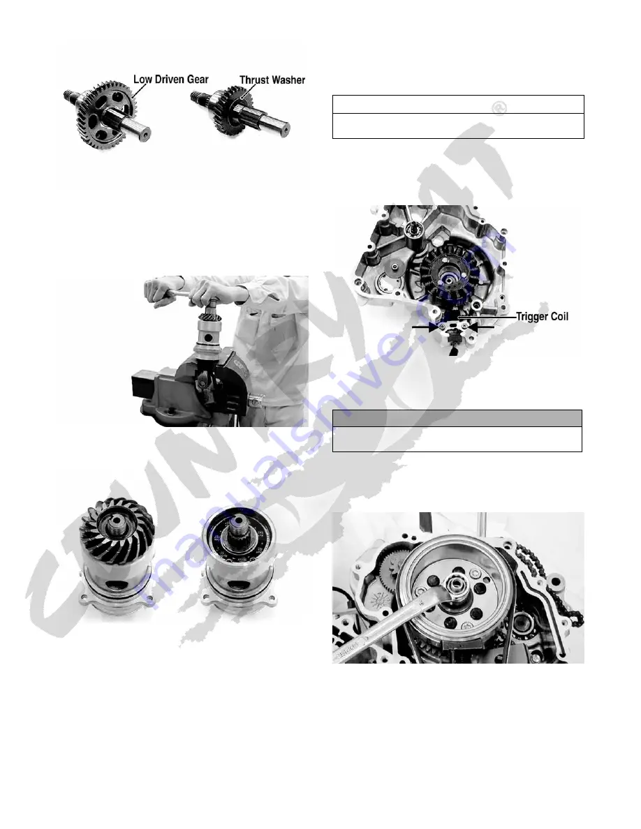
56
KM692A
13. To disassemble the secondary driven bevel gear
assembly, use the following procedure.
A. Secure the universal joint using a suitable vise;
then engage the output end of the shaft with the
universal joint.
KM653
B. Remove the nut securing the driven bevel gear;
then remove the gear. Account for a washer.
KM654
C. Remove the shaft and housing from the universal
joint and remove the shaft from the housing.
NOTE: If left-side components are still attached,
remove the centrifugal clutch/driven pulley.
B. Water Pump
C. Trigger Coil
D. Stator Coil
E. Rotor/Flywheel
14. Remove the right crankcase cover (see Fuel/Lubrica-
tion/Cooling - Water Pump).
15. Remove the trigger coil mounting screws; then
remove the wire set plate.
KM772A
16. Remove the three cap screws securing the stator coil
to the crankcase cover; then remove the stator coil
and trigger coil.
17. Remove the oil-through and spring from the end of
the crankshaft; then hold the rotor/flywheel with an
appropriate holding tool and remove the flywheel nut
and washer.
KM774
18. Install the flywheel puller and crankshaft protector;
then remove the rotor/flywheel. Account for a key
and the starter one-way clutch bearing.
AT THIS POINT
To remove/service the water pump, see Fuel/Lubrica-
tion/Cooling.
CAUTION
Use extreme care to avoid damaging or shorting the
wiring.


