37
IO046A
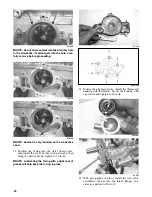
12. Remove the two PTO-side cap screws (A) secur-
ing the engine to the chassis.
0744-860
13. Remove the cap screw (B) securing the upper
MAG-side engine mount to the chassis; then
remove the lower cap screw (C) securing the
engine to the chassis.
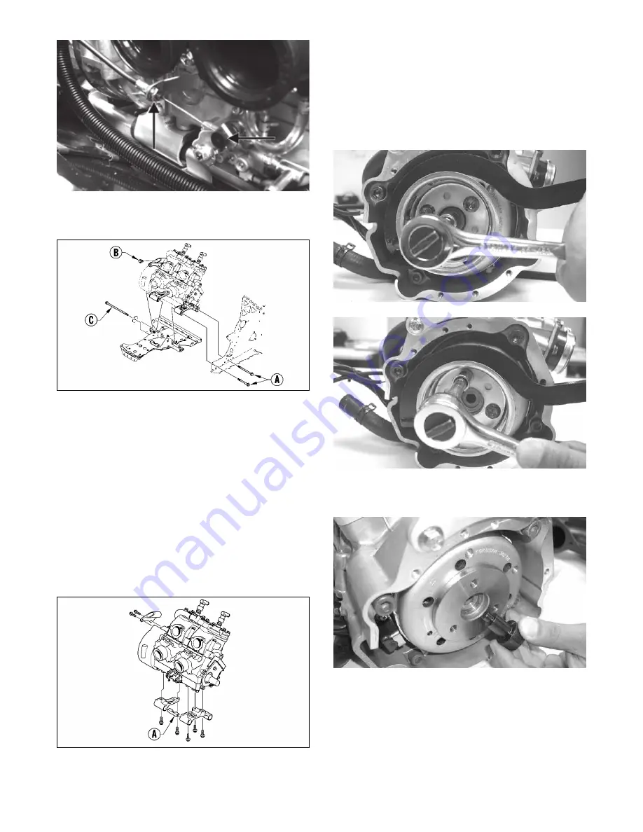
14. Move the engine up far enough to gain access to
the coolant hose clamps securing the hoses to the
lower crankcase and thermostat housing; then
loosen the clamps and remove the coolant hoses.
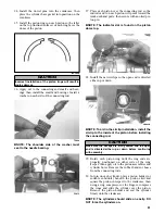
15. Remove the engine from the MAG-side of the
chassis and account for the engine mount spacer
(A) located between the MAG-side and PTO-side
engine mounting bracket; then with the engine
removed, remove the cap screws securing the
engine mounting brackets to the engine.
0744-859
NOTE: For installing purposes, note the location
of the different-length cap screws.
Disassembling Engine
NOTE: It is advisable to loosen the spark plugs
prior to disassembling the engine.
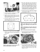
1. Using the Flywheel Spanner Wrench to secure the
flywheel, remove the flywheel cap screw and flat
washer; then remove the three starter pulley cap
screws and remove the pulley.
FC014
FC015
2. Install Flywheel Puller Insert onto the end of the
crankshaft.
FC016
Summary of Contents for 500 Sno Pro
Page 1: ...TM SHARE OUR PASSION Operator s Performance Manual Performance Manual 500 Sno Pro...
Page 2: ......
Page 6: ...NOTES...
Page 22: ...16 NOTES...
Page 68: ...62 NOTES...
Page 92: ...86 NOTES...
Page 93: ...87 NOTES...
Page 94: ...88 NOTES...
Page 95: ...Printed in U S A Trademarks of Arctic Cat Inc Thief River Falls MN 56701 p n 2258 721...


