65
NOTE: After testing the oil pump, the oil pump
must be correctly synchronized with the throttle
bodies (see Synchronizing Oil-Injection Pump).
Testing Oil-Injection Check Valves
In the event an engine problem occurs due to lack of
lubrication, the oil-injection pump check valves should
be tested using a vacuum pump to make sure the check
valves are operating properly.
When testing the check valves, remove them from the
pump assembly.
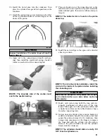
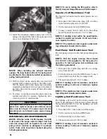
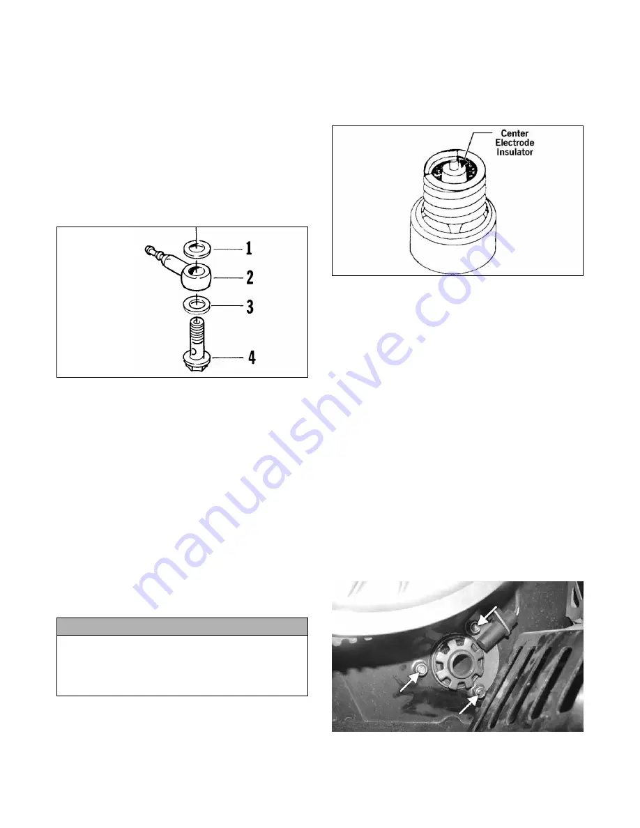
1. Remove the check valves from the oil-injection
pump.
731-551A
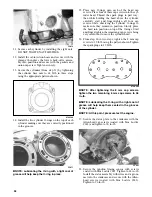
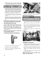
2. Attach the vacuum test pump hose to the check
valve.
3. Squeeze the vacuum pump handle and watch the
pump gauge. The check valve should release at
4.5-5 lb and again reset itself at 3.5-4 lb. If
“release” and “reset” are not within specifications,
replace the check valve.
4. Record the “release” and “reset” readings for the
valve; then perform the test on the other valve.
The “release” and “reset” readings must fall within
specifications and must be within 1.5 lb of each
other. If either or both are not met, replace the
check valves.
5. If the check valves are within specifications but
the oil-injection usage is not, replace the oil-injec-
tion pump.
SPARK PLUGS
Correct gap is 0.7-0.8 mm (0.028-0.031 in.).
Checking Spark Plugs
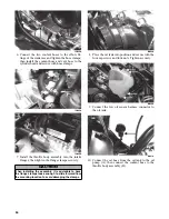
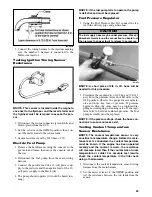
To check spark plug condition and to aid in determin-
ing correct fuel/air mixture, pull the spark plug caps
off the spark plugs, remove the spark plugs, and exam-
ine the condition of the center electrode insulator of
each spark plug.
0725-048
A. TAN or LIGHT BROWN insulator indicates
correct spark plugs (heat range).
B. LIGHT GRAY or WHITE insulator indicates
overheating of the engine. This condition is
caused by a too lean condition, ignition timing
set too high, or incorrect spark plugs (heat
range too hot).
C. BLACK insulator indicates fuel in the combus-
tion chamber is not burning completely. This
condition is caused by a too rich condition.
TRACK DRIVE
Removing
1. Remove the hood and right and left side panels
and set aside; then remove the resonator.
2. Place a suitable safety stand beneath the rear bum-
per taking the weight of the snowmobile off the
rear suspension.
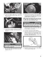
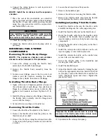
3. Remove the three nuts securing the left side of the
track drive and discard.
RS079A
4. Remove the cap screws securing the slide rail
assembly.
CAUTION
Whenever servicing the oil-injection system, use a
100:1 gas/oil mixture in the gas tank to ensure ade-
quate engine lubrication. Failure to use the 100:1 mix-
ture to the oil-injection system will result in severe
engine damage.
KEY
1. Gasket
2. Check Valve
3. Gasket
4. Union
Summary of Contents for 500 Sno Pro
Page 1: ...TM SHARE OUR PASSION Operator s Performance Manual Performance Manual 500 Sno Pro...
Page 2: ......
Page 6: ...NOTES...
Page 22: ...16 NOTES...
Page 68: ...62 NOTES...
Page 92: ...86 NOTES...
Page 93: ...87 NOTES...
Page 94: ...88 NOTES...
Page 95: ...Printed in U S A Trademarks of Arctic Cat Inc Thief River Falls MN 56701 p n 2258 721...

