3-27
3
8. Rotate the crankshaft clockwise 180° and repeat
steps 5-7 on the other cylinder.
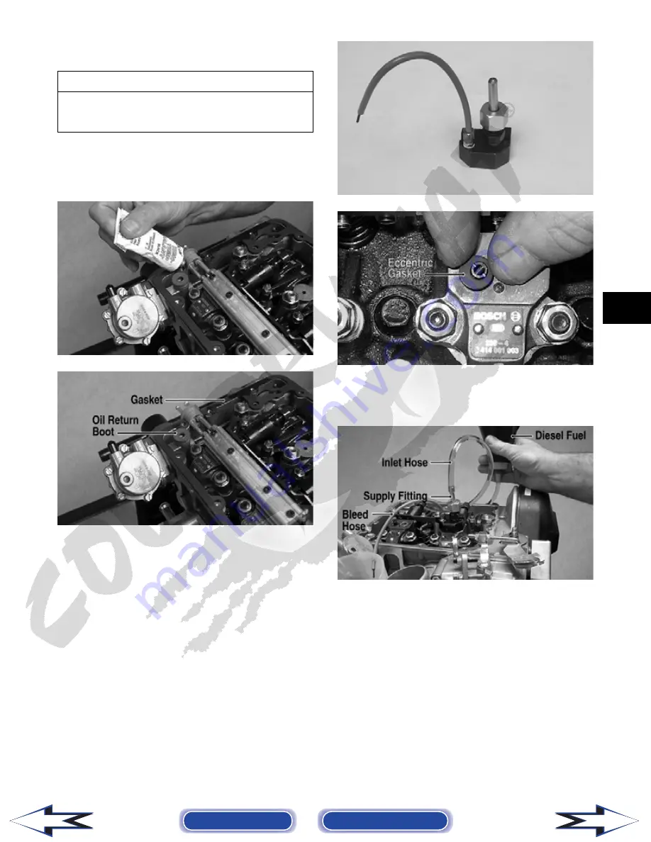
9. Place a small bead of high-temperature sealant on
the fuel rail seal; then carefully install the valve
cover with a new gasket and oil return boot.
Tighten to specifications.
DE406
DE405B
10. Connect the oil pressure switch connector and the
crankcase ventilator hose; then install the air filter
assembly and secure with the existing hardware.
Tighten securely.
11. Install the front body panel; then install the front
rack and splash panels (see Section 8).
STATIC INJECTOR TIMING
To set static injector timing, use the following proce-
dure.
1. Remove the valve cover and fuel rail (see Unit
Injectors in this sub-section).
2. Install the Timing Fuel Block (p/n 0444-234) on
the injector using the eccentric gasket over the
check valve in place of the O-ring.
DE572
DE444A
3. Connect a suitable container filled with clean die-
sel fuel to the supply fitting using an inlet hose;
then place a small cup under the bleed hose.
DE403B
4. Rotate the engine in the direction of rotation
(clockwise) until the #2 (flywheel-side) piston is at
top-dead-center (TDC) on the compression stroke
(reference mark (D) aligned to TDC index mark
(A) and valves closed).
AT THIS POINT
If engine is being assembled, static injector timing
should be adjusted (see Top-Side Components in
this section).
Back to TOC
Back to Section TOC
Next
Back


