14
NOTE: During the bleeding procedure, watch the
reservoir sight glass to make sure there is always a
sufficient amount of brake fluid in the reservoir. Fail-
ure to maintain sufficient amount of fluid in the reser-
voir will result in air being in the system.
5. Repeat step 4 until the brake lever is firm.
Replacing Drive Belt
REMOVING
1. Remove the eight Phillips-head cap screws and four
cap screws securing the footrest cover to the footrest
and front and rear fenders; then remove footrest
cover.
2. Remove the cooling duct.
3. Remove the eight cap screws securing the drive
clutch cover; then remove the cover. Account for a
gasket and two alignment pins.
NOTE: The gasket does not need to be removed
unless it is being replaced or unless additional ser-
vicing is being done requiring its removal.
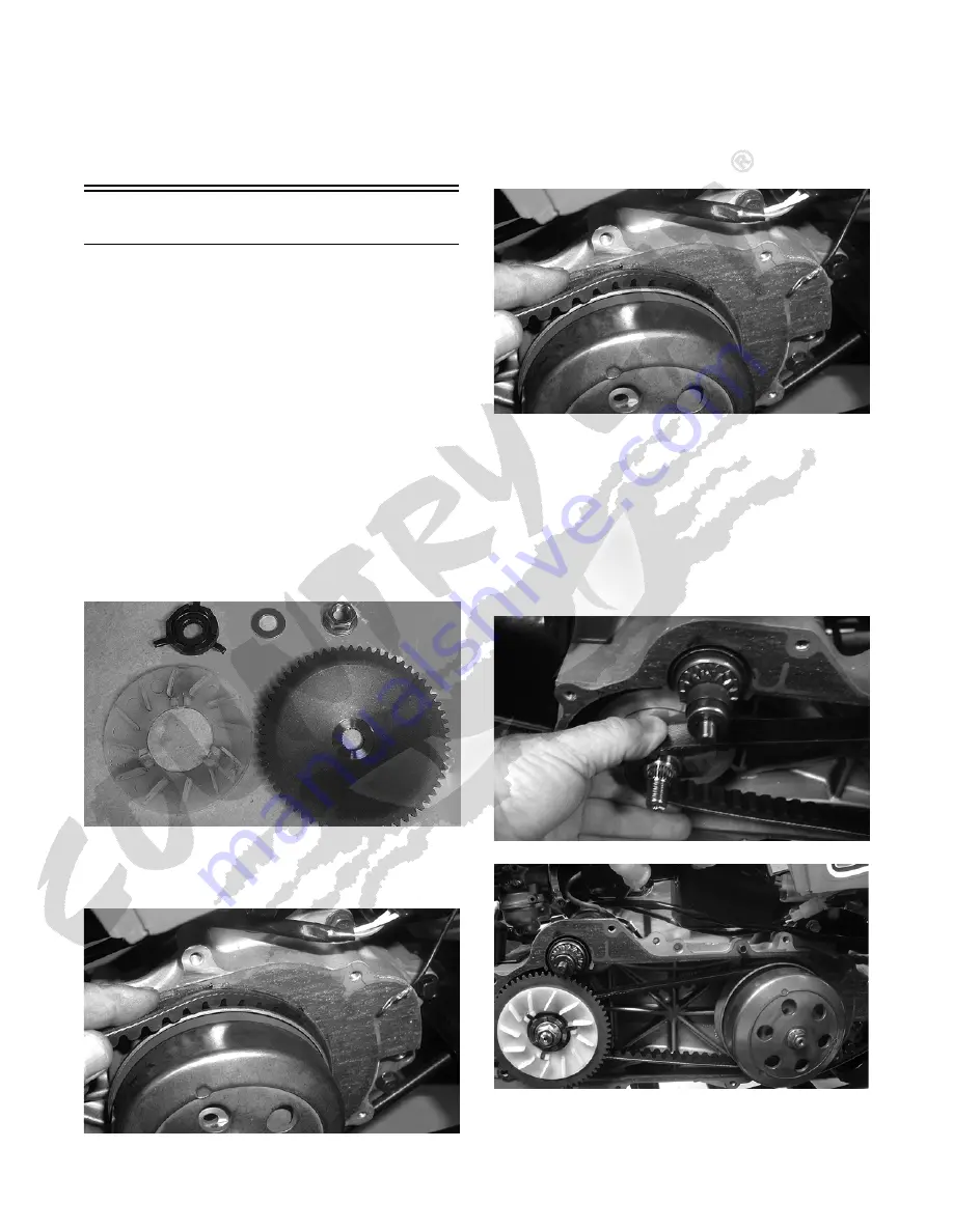
4. Remove the nut securing the stationary drive sheave
to the crankshaft; then remove the stationary drive
sheave. Account for a washer, kick starter ratchet,
and cooling fan.
CD621
5. Open the movable sheave on the driven clutch
assembly with a suitable pry bar or wedge; then
remove the drive belt.
CD624
INSTALLING
1. If removed, place the gasket and two alignment pins
into position on the crankcase.
2. Spread the faces of the driven clutch with a suitable
pry bar or wedge; then when the faces are separated,
insert the drive belt.
CD624
NOTE: If the drive belt has an arrow stamped on the
outer face, it should point forward (direction of rota-
tion).
3. Pinch the drive belt together near its center and slide
the stationary drive sheave over the crankshaft.
Install the washer, kick starter ratchet, and cooling
fan. Secure the stationary drive sheave with a nut
(threads coated with red Loctite #271). Tighten the
nut to 27.5 ft-lb.
CD623
CD619
4. Rotate the drive belt and sheaves until the drive belt
is flush with the top of the driven clutch.


