background image

44

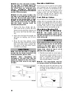
1. Measure the outside circumference

of the drive belt. The belt should be

within the recommended range in

circumference (see appropriate spec-

ifications sheet).

2. Measure the outside width of the

drive belt. The belt should be within

the recommended range in width.

3. Check the belt for cracking, fraying,

etc.

If any of the specifications or conditions

are unsatisfactory, replace the drive belt.

NOTE: Drive belts should be pur-

chased from an authorized Arctic
Cat Snowmobile dealer, as Arctic Cat
drive belts are made to exact specifi-
cations and of quality material. Belts
made by other manufacturers may
not be of the same specifications or
quality and, therefore, usage could
result in poor performance and pre-
mature belt failure.

NOTE: Before starting the snowmo-

bile in extremely cold temperatures,
the drive belt should be removed and
warmed up to room temperature.
Once the drive belt is at room temper-
ature, install the drive belt.

Also, new drive belts have a break-in

period of approximately 25 miles. After

installing a new drive belt, drive the

snowmobile for 25 miles at 3/4 throttle or

less. By revving the engine up and down

(but not exceeding 60 mph), the exposed

cord on the side of a new belt will be

worn down. This allows the drive belt to

gain its optimum flexibility and will

extend drive belt life.

Checking/Adjusting Drive 

Belt Deflection

0746-092

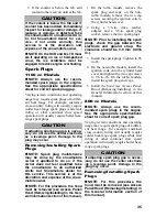
The drive belt must have the proper fit in

the drive clutch and driven pulley. To

check for proper drive belt fit, use the

following procedure.

1. Place a straightedge on the top of the

drive belt. The straightedge should

reach from the drive clutch to the top

of the driven pulley.

NOTE: Make sure the drive belt is

all the way out in the driven pulley
before checking drive belt deflection.

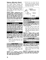
2. Using a stiff ruler centered between

the drive clutch and driven pulley,

push down on the drive belt just

enough to remove all slack and note

the amount of deflection. The deflec-

tion should be within the range of

28.5-31.8 mm (1 1/8-1 1/4 in.).

3. To correct drive belt deflection,

remove the sheave adjuster from the

pulley, remove or add shim washers

to the adjuster, and install the

adjuster.

NOTE: Adding shim washers will

decrease belt deflection and remov-
ing shim washers will increase belt
deflection. Available shim washers
from Arctic Cat are p/n 0648-714
(0.090 in.) - one included in the tool
kit, p/n 0648-715 (0.030 in.), and p/n
0648-716 (0.060 in.).

NOTE: Removing/adding shim

washers may be done by the snow-
mobile owner if qualified to do so. If
the owner does not feel qualified,
take the snowmobile to an autho-
rized Arctic Cat Snowmobile dealer
for this service. This service is at the
discretion and expense of the snow-
mobile owner.

CAUTION

Never run the engine with the drive
belt removed. Excessive revving of the
engine could result in serious engine
damage and drive clutch failure.

Summary of Contents for F 1100 series

Page 1: ...Manual 2013 Operator s Manual F 800 Models F 1100 Models F 1100 Turbo Models M 800 Models M 1100 Models Crossover Mountain Performance Models M 1100 Turbo Models XF 800 Models XF 1100 Models XF 1100 T...

Page 2: ...snow conditions without proper lubrication or additional idler wheels and the following parts Fuel Filter Light Bulbs Windshield Drive Belt Torn or Punctured Upholstery Wear Bars Brake Pads Spark Plu...

Page 3: ...V System 800 cc Models 22 Exhaust Controlled Timing ECT System 800 cc Models 23 Operating Instructions 24 27 Starting and Stopping Engine 24 Braking 25 Emergency Stopping 26 Throttle Ignition Monitor...

Page 4: ...l and Safety Handbook Failure to follow this warning could result in personal injury to yourself or others Personal Injury To avoid injury to yourself and others NEVER operate the snowmobile without f...

Page 5: ...or service is ever required contact an authorized Arctic Cat Snowmobile dealer for professional service At the time of publication all information and illustrations were technically cor rect Some illu...

Page 6: ...013XFNLEUSW S2013F8H68USB S2013M8H3EOSB S2013XFNXPUSO S2013XFNLEUSB S2013F8HLEUSW S2013M8HSPOSG S2013XFNXPUSB S2013XFNTPUSB S2013F8HLEUSB S2013M8HSPOSO S2013M1N3EOSB S2013XFNHCUSW S2013M8H3EUSB S2013M...

Page 7: ...3 Snowmobile Safety Rules...

Page 8: ...ealer to complete warranty claims properly No warranty will be allowed by Arctic Cat Inc if the engine serial number or VIN is removed or mutilated in any way Always provide the snowmobile name VIN an...

Page 9: ...n taining up to 10 ethanol are acceptable gasoline Do not use gasolines containing methanol Recommended Injection Oil 800 cc Models The recommended oil to use in the oil injection system is either Arc...

Page 10: ...r the fuel mixture from the gaso line container into the snowmobile gas tank Engine Break In The Arctic Cat engine when new or rebuilt requires a short break in period before the engine is subjected t...

Page 11: ...coolant tem perature warning icon will begin to flash the TEMP display will continue to flash and the RPM limit of the engine will increase allowing the snowmobile to move without full throttle operat...

Page 12: ...lay either tap the buttons for individual num ber display or push and hold the buttons for rapid number display NOTE During clock setting if nei ther button left right is pushed within a 5 second time...

Page 13: ...of gasoline under normal operat ing conditions Oil Pressure Warning Icon 1100 cc Models The Oil Pressure Warning Icon indicates engine oil pressure not the oil level however if the oil level is low it...

Page 14: ...and one with the needle By pushing the button once again the functions will be reversed By pushing the increment button with speed being displayed for more than two seconds the display will change be...

Page 15: ...els the icon should briefly illuminate each time the key is turned to RUN or START and engine is started then it should go out when the engine starts If the icon stays illuminated on electric start mo...

Page 16: ...is approximately equal to 1 tankful of gasoline under normal operat ing conditions Oil Pressure Warning Icon 1100 cc Models The Oil Pressure Warning Icon indicates engine oil pressure not the oil lev...

Page 17: ...To adjust handlebar tilt use the following procedure 1 Loosen the four cap screws and tilt the handlebar to the desired position Code Trouble 2 Failure in injector s 4 Open or short circuit in barome...

Page 18: ...ny exhaust sys tem component is removed from the engine and the engine is run severe engine damage will result Air Intake Silencer Used in conjunction with the fuel intake system is a specially design...

Page 19: ...ad battery but rather to remove the battery service it and correctly charge it however in an emergency it may be necessary to jump start a snowmobile If so use the following procedure to carefully and...

Page 20: ...fore disconnecting the jumper cables 10 Remove the jumper cables in oppo site order of hook up 4 3 2 1 Be careful not to short cables against bare metal NOTE Have the battery and elec trical system ch...

Page 21: ...ing quality deteriorates or seems to be deterio rating take the snowmobile to an authorized Arctic Cat Snowmobile dealer for shock absorber evaluation and or servicing This service is at the discretio...

Page 22: ...on The engine reverse function offers the operator the convenience of being able to back up the snowmobile rather than hav ing to turn the snowmobile around by hand This feature under most situations...

Page 23: ...icon will illuminate in the speedom eter tachometer and a reverse alarm will sound 2 If the throttle lever is compressed before complete reverse engage ment the engine may shut down Always wait for th...

Page 24: ...er the engine is shut off 2 After shifting from reverse to for ward or from forward to reverse apply the throttle slowly and evenly to allow the driven pulley to engage properly Access Panel Hood Remo...

Page 25: ...l the access panel and hood use the following procedure 1 Position the hood onto the snowmo bile and connect the hood harness connector making sure the harness does not become pinched NOTE On 800 cc m...

Page 26: ...nsists of an exhaust valve assembly mounted to the exhaust side of each cylinder and connected by adjust able cables to an electronic servo mounted beneath the hood NOTE The mounting location of the s...

Page 27: ...automatically adjusts the ignition timing to provide maximum per formance through a variety of operating conditions The ECU receives input on engine RPM demand and exhaust pipe temperature engine cond...

Page 28: ...d is at the recommended level Install and secure the reservoir cover Do not allow mois ture to contaminate the brake system 4 Test the throttle control lever by completely compressing and releas ing i...

Page 29: ...stems including automotive applica tions heat is transferred to the brake fluid The amount of heat transferred during high speed stops and or repeti tive use may be high enough to boil the brake fluid...

Page 30: ...ice forms in the throttle system or if there is some other malfunction of the throttle system result ing in a loss of return spring force the monitor switch will stop the engine when the throttle cont...

Page 31: ...lectri cal features ignition switch emer gency stop switch headlight taillight and brakelight will operate properly Varying Altitude Operation Operating a snowmobile at varying alti tudes requires cha...

Page 32: ...and connect the actuator wiring har ness Tighten screws to 36 in lb 0746 804 4 On the 1100 cc models start the engine and verify proper reverse and forward operation by shifting in and out of reverse...

Page 33: ...reso nator NOTE On the 1100 cc models the resonator gasket s between the exhaust pipe s and resonator must be replaced 7 On the 1100 cc models start the engine and verify proper reverse and forward o...

Page 34: ...System Weekly 14 Check for damage leakage and obstructions Nuts Bolts Fasteners Weekly Check tightness Recoil Starter Weekly Check rope for wear fraying and proper operation Shock Absorbers Weekly 17...

Page 35: ...housing then install the left side access panel Fuel System In Line Fuel Filter 1100 cc Models Arctic Cat recommends that the in line fuel filter be replaced every 5000 miles The filter must be clean...

Page 36: ...800 cc models is recommended espe cially in the last tank of gasoline before storage Arctic Cat Fuel Stabilizer p n 0436 907 should also be added to the last tank of gasoline before storage Fuel Picku...

Page 37: ...NOTE To aid in draining the oil from the reservoir position a funnel between the reservoir and the open ing of the tunnel running board 6 After the oil has drained completely install the drain plug w...

Page 38: ...vel may read too low Always make sure the engine is at operating tem perature before checking the oil 15 Install the access plate and torx head screws beneath the snowmobile then install the hood and...

Page 39: ...heck the gap between the electrode and ground strap The clearance should be 0 9 mm 0 035 in 3 Install the spark plugs Tighten to 96 in lb 4 On the non turbo models install the ignition coils onto the...

Page 40: ...rk plugs heat range too cold NOTE If the center electrode insu lators are light gray white or black and if the oil injection pump synchro nization and ignition timing are cor rect different heat range...

Page 41: ...e cable end to remove any slack then measure the amount of exposed cable from the cable housing to the end of the cable cable drum 0735 516 NOTE The two cable measure ments must be equal in length or...

Page 42: ...h clean the battery posts and cable ends removing all corrosive buildup Replace damaged cables or cable ends NOTE If battery posts or cable ends have a build up of white green powder residue apply wat...

Page 43: ...e battery posts and cable ends with a light coat of multi purpose grease 10 Secure the red positive cable to the positive terminal on the battery using a cap screw lock washer and a flat washer Tighte...

Page 44: ...use of the correct amperage rating 4 Install the fuse block cover and close the access panel Even after replacing a fuse it may con tinue to blow if the cause of the overload is not determined If the...

Page 45: ...is service is at the discretion and expense of the snowmobile owner Bleeding Brake System If the brake lever feels spongy when applied the brake system may need to be bled To bleed the brake use the f...

Page 46: ...oes not feel qualified take the snowmo bile to an authorized Arctic Cat Snowmobile dealer for this service This service is at the discretion and expense of the snowmobile owner NOTE When installing ne...

Page 47: ...ccess panel NOTE When new brake pads are installed a burnishing process is required see Burnishing Brake Pads sub section Burnishing Brake Pads After changing brake pads the new brake pads must be bur...

Page 48: ...g Adjusting Drive Belt Deflection 0746 092 The drive belt must have the proper fit in the drive clutch and driven pulley To check for proper drive belt fit use the following procedure 1 Place a straig...

Page 49: ...heaves Installing Drive Belt NOTE If a new drive belt is being installed see Drive Belt Break In sub section in the General Infor mation section 1 Place the drive belt so the part num ber can be read...

Page 50: ...screws 0745 811 NOTE On RR models using Axle Nut Spanner Wrench p n 0644 558 from the tool kit loosen the right side rear axle nut 0744 067 NOTE On RR models always loosen the right side rear axle nut...

Page 51: ...s rotating check the relationship of the rear idler wheels and the inner track drive lugs If the rear idler wheels are centered between the inner track drive lugs no adjustment is necessary 0745 809 5...

Page 52: ...float shock this adjustment is achieved by increaseing or decreasing the air pressure in the rear arm air shock absorber Adjusting Front Ski Shock Springs The front ski shock springs are individu all...

Page 53: ...edure NOTE When adjusting air pres sure all weight must be removed from the suspension and the shock absorbers must be fully extended 1 Remove the air valve cap from the shock 2 Thread the valve of Sh...

Page 54: ...usted it is highly recommended that at least a minimum of 1 8 in preload on the shock spring be maintained Adjusting Rear Spring Pre Load F Models Proper adjustment of rear spring pre load is necessar...

Page 55: ...d Installing Taillight Brakelight These models are equipped with an LED taillight brakelight If the LED fails it must be replaced To remove and install the LED use the following procedure 746 097B 1 D...

Page 56: ...vertical mark 5 cm 2 in below the horizontal mark on the aiming surface 0745 813 7 Adjust the headlight using the adjusting screw on the backside of the headlight using a 4 mm swivel socket and long...

Page 57: ...e cotter pin then remove the slotted nut and cap screw secur ing the ski assembly to the spindle Remove the ski Account for the rubber damper inserts and washers 3 To increase ski stance place ski sta...

Page 58: ...le on a hard pack trail then immediately drive into deep snow and allow the wear strips to cool Repeat the procedure warming up the wear strips then cooling them down two or three times NOTE The rail...

Page 59: ...lection remove the belt guard then use the fol lowing procedure NOTE It may be necessary to remove a shim washer from between the driven pulley sheaves to allow the driven pulley to close tighter Addi...

Page 60: ...the clutch alignment bar between the drive clutch sheaves 3 Allow the bar to rest on the drive clutch shaft and against the outside edge of the driven pulley stationary sheave NOTE The alignment bar...

Page 61: ...hen remove the plugs connect them to the leads and ground them on the cylinder heads B Pour 29 5 ml 1 fl oz of SAE 30 petroleum based oil into each spark plug hole and pull the recoil starter handle s...

Page 62: ...owmobile with a machine cover or a heavy tarpaulin to protect it from dirt and dust 17 If the snowmobile must be stored out doors position the snowmobile out of direct sunlight then block the entire s...

Page 63: ...2 cycle oil see Gaso line Oil Recommended Injection Oil sub section in the General Infor mation section NOTE After prolonged storage of the 800 cc models Arctic Cat recom mends one tankful of 100 1 g...

Page 64: ...Cat snowmobile dealer WARRANTY PERIOD The emission warranty period for this snowmobile begins on the same date as the standard warranty coverage and continues for 30 months or 2500 miles whichever com...

Page 65: ...nsfer the unused portion of the original warranty to a second party In order to transfer warranty fill out this form completely then return a copy of this form to Arctic Cat Inc Arctic Cat will then p...

Page 66: ...Fold Back Once CHANGE OF ADDRESS OWNERSHIP ARCTIC CAT INC PRODUCT SERVICE AND WARRANTY DEPT P O BOX 810 THIEF RIVER FALLS MN 56701 Place Stamp Here...

Page 67: ...ou are in a location away from your selling dealer warranty may be performed by any authorized Arctic Cat Snowmo bile dealer The authorized Arctic Cat Snowmobile dealer will examine the snowmobile or...

Page 68: ...Printed in U S A Trademarks of Arctic Cat Inc Thief River Falls MN 56701 p n 2259 386 Phone 218 681 9851 U S 204 982 1656 Canada TM...

Reviews: