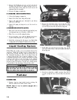
109
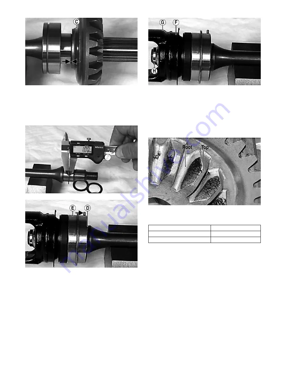
MT011B
3. If installing the existing shaft, start with the shims
removed during disassembly or if installing a new
shaft, start with approximately 1.0 mm shims at point
(D); then install the output drive shaft bearing (E)
making sure the locating pin is directed toward the
center of the shaft.
MT012
MT008A
4. Install a new seal (F), output yoke (G), and nut (H)
and tighten to 74 ft-lb.
MT008B
NOTE: Do not use a new lock nut at this time as this
procedure may have to be repeated.
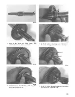
5. Place the assembled shaft into the left crankshaft
case; then lightly coat the gear teeth with machinist’s
lay-out dye. Rotate the shafts through several rota-
tions in both directions. Gear contact should extend
from the root to the top of the gear teeth.
MT016A
6. To adjust tooth contact, use the following chart to
correctly shim the driven shaft.
7. After correct tooth contact is established, proceed to
Checking Backlash in this sub-section.
Checking Backlash
1. If removed, install the secondary drive/bevel gear
shaft into the crankcase; then tighten the nut to 59 ft-
lb.
2. Install the secondary drive bearing support; then
install the secondary driven output shaft into the
crankcase.
3. Mount the dial indicator so the tip is contacting a
tooth on the secondary drive bevel gear.
4. While rocking the drive bevel gear back and forth,
note the maximum backlash reading on the gauge.
Tooth Contact
Shim Correction
Contact at Top
Increase Shim Thickness
Contact at Root
Decrease Shim Thickness
Summary of Contents for PROWLER HDX 2015
Page 3: ......
Page 191: ...188 NOTES...
Page 192: ...Printed in U S A Trademarks of Arctic Cat Inc Thief River Falls MN 56701 p n 2260 410...


