19
PR765A
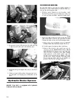
7. Remove the steering shaft housing and shaft from the
steering support and intermediate shaft; then remove
the intermediate shaft from the EPS input shaft.
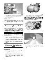
8. Remove four cap screws securing the EPS assembly
to the frame; then remove the cap screw securing the
rack coupler to the EPS output shaft.
PR761A
NOTE: No repairs are authorized on the EPS
assembly and it must be replaced as a complete
assembly.
INSTALLING
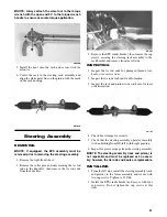
1. Align the slot in the rack coupler to the notch in the
frame (front wheels centered).
PR766A
2. Rotate the EPS shaft to align the index (flattened)
spline with the slot in the rack coupler.
PR776A
NOTE: Alignment need only be approximate as
final alignment is not possible until the EPS is
engaged with the coupler.
3. Install the EPS assembly into the coupler turning the
EPS shaft slightly to align the index spline; then seat
the EPS firmly onto the frame.
4. Install four cap screws securing the EPS assembly to
the frame and tighten to 35 ft-lb.
5. Install the cap screw in the EPS to rack coupler and
tighten to 11 ft-lb.
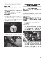
6. Connect the two electrical connectors; then align the
slot in the intermediate steering shaft coupler to the
index (flattened) spline on the EPS input shaft and
install. Install but do not tighten the cap screw.
PR759B
7. Install the steering shaft housing with steering shaft
connecting the steering shaft and intermediate shaft
first; then slide the housing into place on the steering
support.
8. Secure the steering shaft housing to the frame with
four cap screws and nuts. Tighten the 6 mm nuts to 8
ft-lb and the 8 mm nuts to 20 ft-lb.
Summary of Contents for PROWLER HDX 2015
Page 3: ......
Page 191: ...188 NOTES...
Page 192: ...Printed in U S A Trademarks of Arctic Cat Inc Thief River Falls MN 56701 p n 2260 410...


