99
4. With the ignition off, disconnect the battery leads
from the battery. Carefully remove the connector
from the ECM. Disconnect the 8-pin connector from
the EPS assembly. Check for resistance on the
Grey/Yellow wire (EPS to ECM); then check for
resistance on the White/Grey wire (EPS to ECM).
For each wire, the meter should read less than one
ohm. If readings are erratic or out of specification,
check the physical condition of the pins, connectors,
and wires. Repair or replace as necessary.
NOTE: If after completing the preceding tests and
possible solutions with normal results, an EPS issue
persists with active DTCs C1301-C1305,1316, or
C1326-C1329 confirmed by CATT II, the EPS assem-
bly must be replaced (see Steering/Body/Controls).
Ignition Switch
To access the ignition switch, dash switches, front acces-
sory connectors, and front switched accessory connector,
the dash must be unfastened and slid to the rear.
VOLTAGE
1. Set the meter selector to the DC Voltage position.
2. Connect the red meter lead to the red wire; then con-
nect the black meter lead to ground.
3. Meter must show battery voltage.
NOTE: If the meter shows no battery voltage, trou-
bleshoot the main 30 amp fuse, the battery, or the
main wiring harness.
4. Connect the red meter lead to the brown/black wire;
then with the black lead grounded, turn the ignition
switch to the ON position. The meter must show bat-
tery voltage.
5. Connect the red meter lead to the yellow/green wire;
then with the black lead grounded, turn the ignition
switch to the START position. The starter should
engage and the meter must show battery voltage.
NOTE: When the starter is engaged, battery voltage
will be approximately 10.5 DC volts.
Ignition Coil
The ignition coils are mounted to the lower radiator
frame (rear cylinder) and the forward heat shield (front
cylinder). Remove the rear body panel and cargo box to
access the coils.
Primary Voltage
1. Set the meter selector to the DC Voltage position;
then disconnect the connector from the coil to be
tested.
2. Connect the red tester lead to the orange wire and the
black tester lead to ground.
3. Turn the ignition switch to the ON position. The
meter must show battery voltage.
Secondary Voltage
1. Connect the primary ignition coil connector. Remove
the spark plug cap from the spark plug.
2. Connect the spark plug cap to Ignition Test Plug or
other suitable tool; then ground the tool away from
the spark plug hole. While turning the engine over,
check for sufficient spark.
RESISTANCE
NOTE: For this test, the meter selector should be set
to the OHMS position.
Primary Winding
1. Disconnect the primary connector and connect the
red tester lead to one terminal; then connect the black
tester lead to the other terminal.
2. The meter reading must be within specification.
NOTE: Secondary coil resistance checks are not rec-
ommended. An internal diode in the coil prevents
accurate secondary resistance measurements.
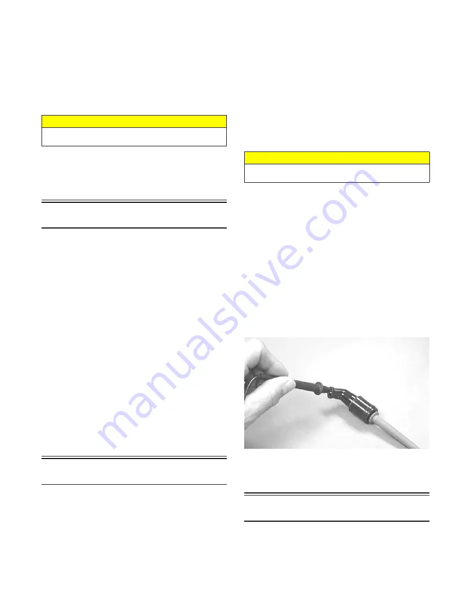
Spark Plug Cap
1. Connect the red tester lead to one end of the cap;
then connect the black tester lead to the other end of
the cap.
AR603D
2. The meter reading must be within specification.
NOTE: If the meter does not show as specified,
replace the spark plug cap.
Ignition Timing
The ignition timing cannot be adjusted; however, verify-
ing ignition timing can aid in troubleshooting other com-
ponents. To verify ignition timing, use the following
procedure.
CAUTION
Never disconnect the ECM connector with the battery
cables installed onto the battery.
CAUTION
Always disconnect the battery when performing resis-
tance tests to avoid damaging the multimeter.


