16
WC810
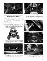
6. Remove the movable sheave and V-belt and any belt
threads or debris in the CVT housing or sheaves.
WC809
NOTE: If threads are fouling the drive clutch, it may be
necessary to remove the clutch and disassemble it to free
threads from the center bearing (see Engine/Transmis-
sion - Removing Right-Side Components).
CHECKING
Use the Drive Belt Gauge to identify any abnormal wear.
Measure across the top of the V-belt (in multiple loca-
tions) using a Vernier caliper. Do not squeeze the belt as
doing so may produce an inaccurate measurement. The
V-belt must be at least 28.5 mm at any point.
INSTALLING
NOTE: If any drive clutch or driven clutch compo-
nent has been replaced or the technician is unsure of
shim quantity/placement, clutch offset must be veri-
fied (see Engine/Transmission - Installing Right-Side
Components steps 10-13).
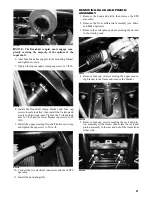
1. Making sure the directional arrow on the belt is
aligned with engine rotation, place the new drive belt
in place on the drive clutch; then making sure the
“X” marks are aligned, install the movable sheave on
the driven clutch.
WC667
WC810A
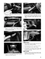
2. Secure the driven clutch with the cap screw (A),
washer (B), and alignment shim(s) (C); then tighten
to 60 ft-lb.
WC741A
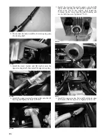
3. Place the alignment pins and new gasket on the clutch
housing; then install the CVT cover, CVT exhaust pipe
mount, and air filter bracket and secure with the cap
screws. Tighten in a crisscross pattern to 8 ft-lb.
4. Connect the exhaust duct and tighten the boot clamp
securely.
5. Install the rear shock absorber and secure with the
cap screws. Tighten the upper cap screw to 40 ft-lb
and the lower cap screw to 35 ft-lb.
NOTE: Drive belts require a break-in period (see
Drive Belt Break-In Procedure in the General Infor-
mation Section).
CAUTION
Failure to properly break-in a new drive belt will result in
premature belt failure.


